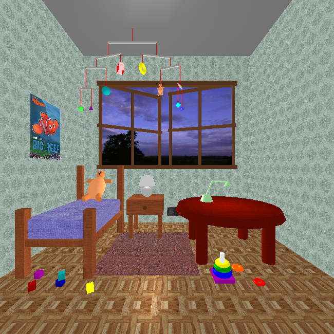
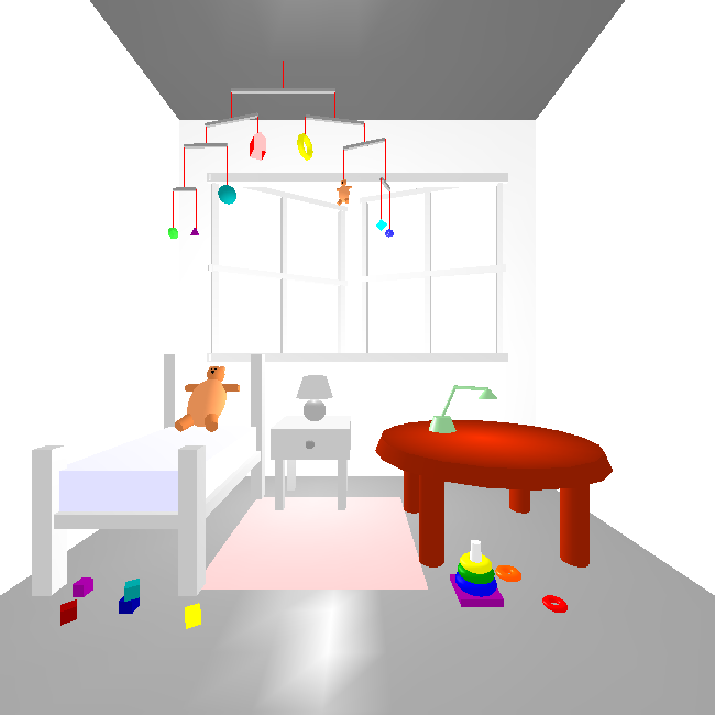
Texture mapping was one of the major innovations in CG in the 1990s. It allows us to add a lot of surface detail without adding a lot of geometric primitives (lines, vertices, faces). Think of how interesting Caroline's ``loadedDemo'' is with all the texture-mapping.
As with everything in computer graphics, most of what I know about texture mapping I learned from an early edition of Angel's book, so check that first. Unfortunately, the edition I read had one of his weakest chapters, because it didn't do a very good job of connecting the theory with the OpenGL code. A more practical presentation is a chapter of the Red Book (the Red OpenGL Programming Guide). You're encouraged to look at both.
In this reading, we'll start with some conceptual overview, then quickly look at practical examples, then we'll tour through the many settings, parameters and situations there are to consider.
Texture mapping paints a picture onto a polygon. Although the name is texture-mapping, the general approach simply takes an array of pixels and paints them onto the surface. An array of pixels is just a picture, which might be a texture like cloth or brick or grass, or it could be a picture of Homer Simpson. It might be something your program computes and uses. More likely, it will be something that you load from a orginary image file.
Demos: These all are part of the 307 demos list. You need not worry about the code yet. We'll look at it a bit later.
These are textures that are simple arrays that we have computed in JavaScript. They're mapped onto either a plane, a box, a cylinder, a sphere, or a teapot.
These are textures that are loaded from separate image files.
Conceptually, to use textures, you must do the following:
(s,t) for each
vertex of your geometry
The graphics system ``paints'' the texture onto the polygon.
Texture mapping is a raster operation, unlike any of the other things we've looked at. Nevertheless, we apply textures to 2D surfaces in our 3D model, and the graphics system has to figure out how to modify the pixels during rasterizing (AKA scan conversion).
Since texture-mapping happens as part of the rasterizing process, let's start there.
When the graphics card renders a polygon, it (conceptually)
Note: standard terminology is that the polygon is called a fragment (since it might be a fragment of a Béezier surface or some such). Thus, the graphics card applies a texture to a fragment.
This all happens in either in the framebuffer or an array just like it.
To do texture mapping, the graphics card must
We can have 1D or 2D textures. The texture parameters will be in the range [0,1] in each dimension. Note that if your texture array isn't square and your polygon isn't square, you may have to deal with changes in aspect ratio.
Your texture is always an array and therefore is always a rectangle. Mapping a texture to rectangles (as OpenGL objects) is fairly easy; mapping it to other shapes is likely to cause distortion. We'll need to be careful in those cases.
Associate each vertex of our polygon with a texture parameter, just
like we associate it with a normal, a color, and so forth. Three.js has
properties of a Geometry object devoted to representing the texture
coordinates for each vertex of a triangular face.
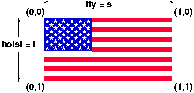
How do the texture coordinates relate to the 2D array of texels? This is easiest to explain with a picture such as the one above.
[0][0] is the same as texture
coordinates (0,0).
[0][RowLength], we get to texture
coordinates (1,0). This may seem odd, but it's true.
[ColLength][0], we get to texture
coordinates (0,1). Again, this may seem odd, but it's
true.
[ColLength][RowLength] corresponds to texture coordinates
(1,1).
Conventionally, the texture coordinates are called (s,t),
just as spatial coordinates are called (x,y,z). However, they can also
be called Thus, we can say that s goes along the rows of the
texture (along the ``fly'' of the flag). The t coordinate goes along
the columns of the texture (along the ``hoist'' of the flag).
Although you will often use the entire texture, so that all your texture coordinates are 0 or 1, that is not necessary. In fact, because the dimensions of texture arrays are required to be powers of two, the actual image that you want is often only a portion of the whole array.
The computed US flag array has that property. The array is 256 pixels wide by 128 pixels high, but the flag itself is 198 pixels wide by 104 pixels high. Thus, the maximum texture coordinates are:
fly = 198/256 = 0.7734 hoist = 104/128 = 0.8125
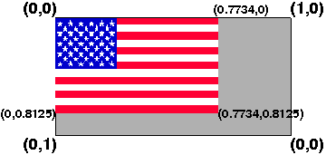
The result might look like the image above.
Of course, we also need to ensure that the rectangle we are putting the flag on has the same aspect ratio as the US flag, namely: 1.9. See the official US flag specification.
The texture parameters can also be greater than 1, in which
case, if we use \url{GL_REPEAT}, we can get repetitions of the
texture. If s is some parameter where 0 < s <
1, specifying some part of the texture partway along,
then 1+s, 2+s and so on are the same location in
the texture. Move this par
It's now time to look at the code for our basic demos.
These are textures that are simple arrays that we have computed in JavaScript. They're mapped onto either a plane, a box, a cylinder, a sphere, or a teapot.
These are textures that are loaded from separate image files.
w × h × 3 bytes giving the R, G, B values for
each pixel.
\end{itemize}
\raggedright It's standard to store the image in top-to-bottom,
left-to-right order. I got this info from
\url{http://astronomy.swin.edu.au/~pbourke/dataformats/ppm/}
\end{itemize}
\end{itemize}
For TW, we will always use PPM format. You can convert images to/from PPM
format to other formats using Windows, Mac or Linux graphics programs or
various Linux commands, such as:
\begin{itemize}
\item ppmtogif
\item ppmtojpeg
\item bmptoppm
\item *topnm
\item pnmto*
\end{itemize}
PNM is a ``portable anymap'' file; the programs seem to be able to guess
whether it's black and white (PNB), grayscale (PGM) or color (PPM).
\subsection{Demo}
\begin{itemize}
\item Start Fireworks
\item Draw something
\item Save (default is PNG, so that's fine)
\item copy it to Puma, say with Fetch or WinSCP.
\item convert to PPM:
\begin{verbatim}
% display foo.png
% pngtopnm -verbose foo.png > foo.ppm
% display foo.ppm
\end{verbatim}
\item Run QuadPPM.py foo.ppm
\end{itemize}
\subsection{Loading Images}
We'll explore the code of \url{QuadPPM.py}.
\begin{itemize}
\item You can read in an image from a file and use it as a texture.
\item You should read the file in just once, so don't call \url{twTex2D}
from your display function.
\item Note that most glut objects don't have pre-defined texture
coordinates. Only the teapot does. You can generate them for the
others, using a fairly incomprehensible interface. We'll try to learn
more about this as the semester goes on.
\end{itemize}
\section{Binding Textures}
For additional speed when using several textures, you can load all the
textures, associating each with an integer identifier (just like display
lists) and then referring to them later.
\textbf{Setup steps:}
\begin{itemize}
\item Ask for a bunch of identifier numbers:
\begin{alltt}
glGenTextures(num_wanted,result_array);
\end{alltt}
\item Then, for each texture you want, get one of the numbers out of the
array and:
\begin{alltt}
glBindTexture(GL_TEXTURE_2D, textureNumber);
glTexEnvf(GL_TEXTURE_ENV, GL_TEXTURE_ENV_MODE, something);
glTexParameteri(GL_TEXTURE_2D, GL_TEXTURE_MAG_FILTER, something);
glTexParameteri(GL_TEXTURE_2D, GL_TEXTURE_MIN_FILTER, something);
glTexParameteri(GL_TEXTURE_2D, GL_TEXTURE_WRAP_S, something);
glTexParameteri(GL_TEXTURE_2D, GL_TEXTURE_WRAP_T, something);
glPixelStorei(GL_UNPACK_ALIGNMENT,1);
glTex2D(...);
or
twTex2D(...);
\end{alltt}
\end{itemize}
\textbf{Reference step:} When you want a texture, just:
\begin{alltt}
glBindTexture(GL_TEXTURE_2D, textureNumber);
\end{alltt}
As a convenience, you can replace each of the texture steps with
\begin{alltt}
twLoadTexture(textureIDs[n], filename);
\end{alltt}
However, this function uses \url{GL_MODULATE}, \url{GL_REPEAT} and
\url{GL_LINEAR}, which may not be what you want.
Demos: \url{TextureBinding.cc} and \url{USflag-binding.cc}. Try spinning
either of these. Notice how relatively quick they are. This is because
the texture is already loaded into memory on the graphics card, so almost
nothing needs to be sent down the pipeline to draw the next frame of
animation.
\subsection{Saving Images}
You can also save the contents of the framebuffer as a PPM file. Just hit
the ``S'' key. This is accomplished thanks to an interesting function
\begin{alltt}
void glReadPixels( GLint x, // raster location of first pixel
GLint y,
GLsizei width, // dimensions of pixel rectangle
GLsizei height,
GLenum format, // GL_RGB
GLenum type, // GL_UNSIGNED_BYTE
GLvoid *pixels );
glReadPixels(0,y,width,1,GL_RGB,GL_UNSIGNED_BYTE, (GLvoid *) pixels);
\end{alltt}
The file is saved as \url{saved_image01.ppm} in the current directory. If
you hit ``s'' again, you get \url{saved_image02.ppm} and so forth. In
honor of family and friends weekend, convert these to PNG and put them on
your web page! Or email them!
Note that PPM files are big. In many of our examples, the
framebuffer is 500 by 500. The file size is therefore \[
500\times500\times3+\mbox{\textrm{len(P6500 500 255)}}+1 = 750014 \]
\begin{verbatim}
% ppmtojpeg -v saved-frame01.ppm > saved-frame01.jpg
ppmtojpeg: Input file has format P6.
It has 500 rows of 500 columns of pixels with max sample value of 255.
ppmtojpeg: No scan script is being used
% ls -l saved-frame01.*
-rw-rw-r-- 1 cs307 cs307 25290 Nov 7 00:06 saved-frame01.jpg
-rw-r--r-- 1 cs307 cs307 750014 Oct 31 14:33 saved-frame01.ppm
\end{verbatim}
The JPG is a bit smaller! It's 1/30th the size in this case, but your
mileage may vary.
Since you have a finite filespace quota, manage your space carefully.
Once you save a frame, you might convert it to a compressed format
(probably PNG or JPEG) and then discard the PPM file.
\section{Texture Mapping using Modulate}
When you texture-map using \url{GL_MODULATE}, you have to think about the
color of the underlying surface. In particular, if you're using material
and lighting, you have to use material and textures.
Caroline's texture tutor can help:
\url{~cs307/public_html/demos/textureTutor}
\section{Texture Mapping Onto Odd Shapes}
\subsection{Triangles}
There are actually two choices here. If you want a triangular region of
your texture, there's no problem, just use the texture coordinates as
usual. If you want to squeeze one edge of the texture down to a point, it
would seem that all you have to do is use the same texture coordinates for
both vertices, but that yields odd results. Instead, you can use
linear B\'ezier surfaces to make a triangular region.
Demo: \url{TexturemapTriangles.cc}
\iffalse
\subsection{Circles}
It might not seem that you'd want to do this, but consider texture-mapping
onto the ends of a cylinder.
The key issue is, of course, the mapping from the rectangle to the
circle. There are infinitely many. Here are just two:
\resizebox{0.9\linewidth}{!}{\includegraphics{circle-square.eps}}
I have some demos of these (\url{~cs307/pub/distrib/cylinder-flag.c}), but
the code is incomprehensible.
\fi
\subsection{Cylinders}
If mapping onto a curved surface, we usually represent the surface with
parametric equations and map texture parameters to curve parameters. For
example, a cylinder:
\begin{eqnarray*}
x &=& r\cos(2\pi u)\\
y &=& r\sin(2\pi u)\\
z &=& v/h
\end{eqnarray*}
With the easy mapping:
\begin{eqnarray*}
s=u\\
t=v
\end{eqnarray*}
Demo: \url{CylinderFlag.cc} This shows how to put a 2D texture onto a
non-planar figure. It uses the US flag, since it's easy to see the
orientation of the texture. Essentially, we have to build the figure
ourselves out of vertices, so that we can define texture coordinates for
each vertex. There are two ways to put a flag onto a cylinder: with the
stripes going around the cylinder or along its length. This demo does
either; the ``l'' keyboard callback switches the orientation.
Understanding this code is not easy, but it really only requires
understanding polar/cylindrical coordinates. The texture coordinates are
relatively straightforward.
\subsection{Bezier Surfaces}
We've already seen this, and we got another dose of it when we looked at
mapping onto triangles, but let's look at it again.
To map onto a surface with material and lighting, consider:
Demo: \url{LitUSFlag.cc}
\subsection{Globes}
In general, mapping a flat surface onto a globe (sphere) is bound to produce odd
distortions. It's essentially a 3D version of the problem of mapping a
rectangle onto a circle.
The reverse mapping is interesting to contemplate: namely a flat rectangle
that shows the surface of the globe. This is a problem that cartographers
have wrestled with for years. Indeed, both of the examples I gave above
for circles and squares have equivalents in cartography.
The distortion problem presents several tradeoffs, the most important of
which is shape distortion versus area distortion.
\begin{itemize}
\item area: To preserve the equal-area property, you have to compress the
lines of latitude, particularly those far from the equator. A famous
current example is the \textbf{Peters} projection.
\item shape: To preserve shape, you end up expanding the lines of
latitude, particularly those far from the equator. One important side
effect of preserving shape is that a straight line on the map is a great
circle, which makes these maps better for navigation. A famous current
example is the \textbf{Mercator} projection.
\end{itemize}
Let's spend a few minutes discussing the pros and cons of these. There
are some good web pages linked from the course home page.
To texture-map a globe, I created a globe by hand, iterating from the
north pole (π) to the south pole (-π) and from 0 longitude around
to 2π longitude. I converted each (longitude,latitude) pair into
(x,y,z) values but also made a (s,t) texture-map pair. This works pretty
well except possibly at the poles.
Math:
\begin{eqnarray*}
x &=& \cos(\mathrm{latitude})*\cos(\mathrm{longitude})\\
y &=& \sin(\mathrm{latitude})\\
z &=& \cos(\mathrm{latitude})*\sin(\mathrm{longitude})\\
s &=& 1-\mathrm{longitude}/2\pi \\
t &=& 1-\mathrm{latitude}/\pi+\pi/2\\
\end{eqnarray*}
Demo: \url{GlobeTexture.cc}
\iffalse
\section{Additional Demos}
In the \url{~cs307/pub/demos} directory, we have:
\begin{itemize}
\iffalse
\item \url{texture-squares} which shows some effects of different uses of
the texture coordinates, clamping and repeating and the like.
\fi
\item \url{11-USFlag-binding} which loads several BMP files and maps them
onto the sides of some cubes, which it then scatters about
\end{itemize}
\fi
\end{document}
The idea is to map a buffer of information onto a region of the framebuffer, thereby affecting the pixels.
These topics and techniques are covered in the Dirksen book; we'll address them later.
© Scott D. Anderson
This work is licensed under a Creative Commons License
Date Modified:

