|
CS 332
Assignment 4 Part 2 Due: Thursday, October 17 |
|
The second part of this assignment contains a problem related to the Ikeuchi & Horn algorithm
for recovering 3-D shape from shading, and a second problem for which you will write a 500-word
reflection on the papers that were discussed in class, by Motoyoshi et al. (2007) and
Anderson & Kim (2009). The code files for Problem 1 are stored
in the /home/cs332/download/shading subdirectory on the CS file server.
Preliminaries
Before starting Problem 1, we will explore the (f,g) representation of surface
orientation, the Reflectance Map R(f,g) for different light source directions,
and the dependence of the pattern of image intensity on surface shape, reflectance, and
illumination. First execute the showSP script. Four windows will appear, which
can be moved around and expanded so that they can easily e viewed all at once. The windows
show (1) a colorful mesh figure depicting a sphere, (2) a shaded image of a sphere illuminated
by a point source of light, (3) a shaded image displaying the value of f at each
location of the image (stored in the matrix fmap), and (4) a shading image
displaying the value of g at each location of the image (stored in the matrix gmap).
Use the Pixel Region Tool to examine the values of f and g for the
surface orientations that you see on the surface of the colored sphere. The shaded sphere
demonstrated the ambiguity of recovering 3-D shape from shading - a single image intensity
value can arise from a family of possible surface orientations. The Reflectance Map
R(f,g) specifies the image intensity that is expected for each surface
orientation, given a known light source position and known surface properties.
The showCylinder function has a single input that specifies the direction of
a point light source, expressed as a value of f for the surface orientation
that faces directly toward this source. This function displays the image of a cylindrical
Lambertian surface illuminated by this source, the corresponding Reflectance Map, a
cross-section of the intensity values across the image, and a cross-section of the
f values that correspond to the surface orientations across the cylinder.
Observe the results for a light source direction that is 20\deg away from the
direction to the viewer:
showCylinder(0.353)
How would the appearance of the four figures change if the angle between the viewer
and light source were increased to 45\deg? You'll first need to figure out the
correct value of f to use in this case - consider how the value of f
is determined using stereographic projection. Then predict how the four figures should
change before executing showCylinder with the new value of f.
How would the appearance of the fours figures change if the angle to the light source were
increased to 90\deg (i.e. light source coming in from the right)?
Problem 1: The Ikeuchi and Horn Shape from Shading Algorithm
In class, we described an algorithm for recovering 3-D shape from shading proposed by
Ikeuchi and Horn. In this problem, you will work with an implementation of a simplified version
of the algorithm that assumes that the surface is constant in the vertical direction so that
g = 0 everywhere on the surface. Code for running some simulations of this
algorithm can be found in the shadingScript.m code file.
Part a: For the case of a cylindrical surface illuminated by a light
source that is at an angle of 20° from the viewer (Example 1 in
shadingScript.m), the initial f values given as input to the
algorithm include known f values at the rightmost boundary of the cylinder
and at the location of the shadow boundary on the left side of the cylinder. All other
f values are initially set to 0. After only one iteration of the algorithm,
all of the f values between the two known points are changed. What caused
these values to change from the initial zero values, during the first iteration?
Hint: what are all the sources of constraint used by the algorithm?
Part b: In the shadingScript.m script, Example 2 is similar
to Example 1, except that the light source direction is changed to 45°. Examine the
results of running Example 2, describe any differences that you see from Example 1, and
explain why these differences arise.
Part c: Example 3 in shadingScript.m uses the input image
that was created using a light source direction of 45° away from the viewer, but
specifies an incorrect light source direction of 20°. Carefully observe the final
results obtained in this case. In particular, examine the true and computed f
values and shape displayed overlaid in the lower right corner of the results window.
How do the true and computed f values and shape differ? Explain why these
differences arise.
Problem 2: Recovering Surface Reflectance Characteristics
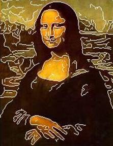
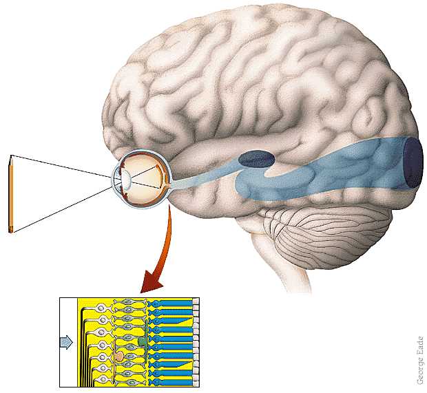
In class, we discussed papers by Motoyoshi et al. (2007) and Anderson & Kim (2009) related to the computation and perception of the gloss and lightness (albedo) of surfaces in the environment. In a short essay of about 500 words, reflect on what you learned from these papers. Your reflection should include some discussion of what you learned about what (valid) visual cues and general constraints can be used to compute surface gloss and lightness from a digital image, and what you concluded from these papers about how the human visual system recovers these surface properties from the retinal image. It may help to imagine that you would like to study this problem further yourself, and want to summarize the "take home message" from these papers that will guide your future work.
Submission details: Hand in a hardcopy of your answers to the problems here. There is no need to submit an electronic copy of any files.