|
CS 332
Observer Motion Lab Due: Thursday, October 25 |
|
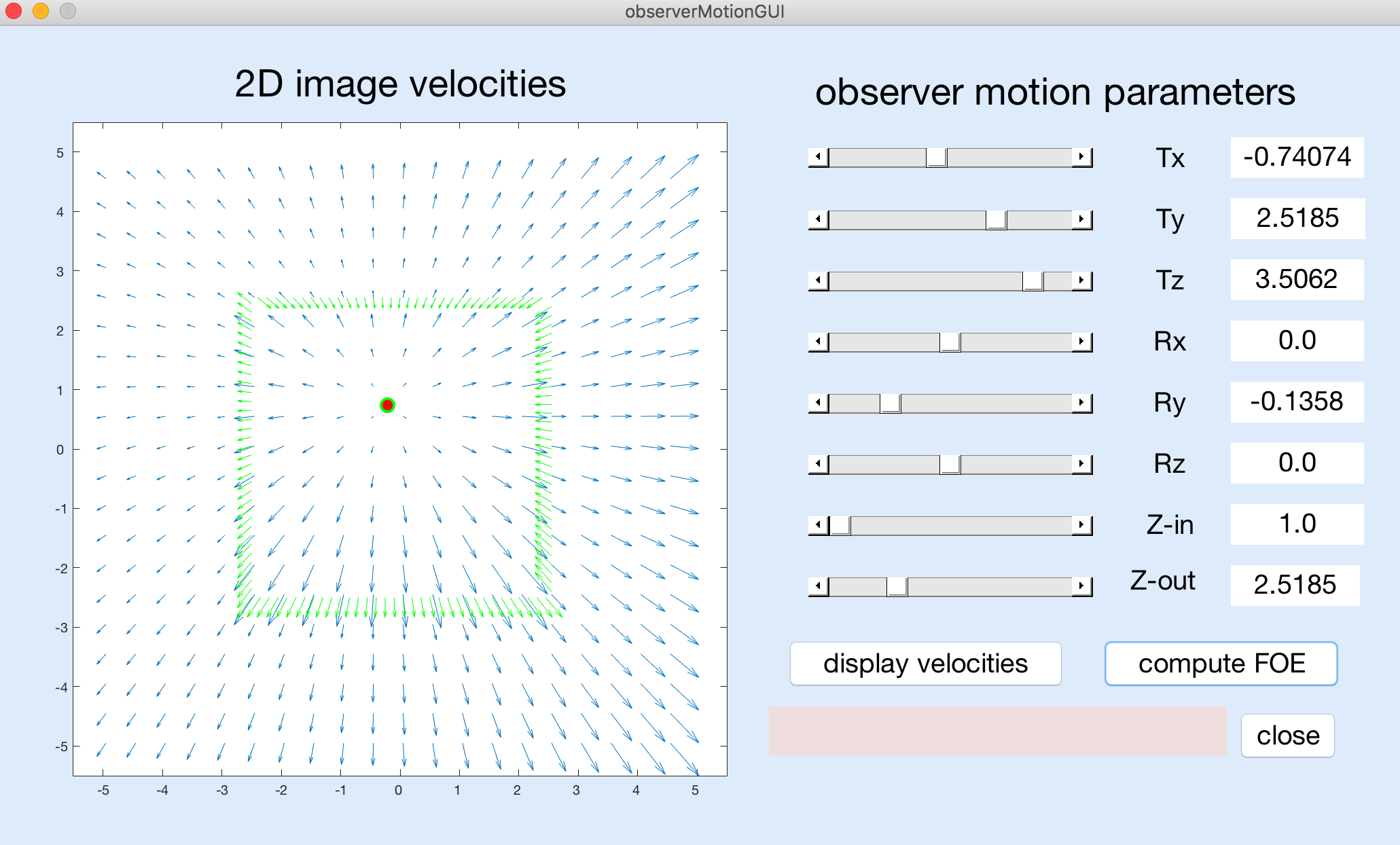
In this lab, you will explore the 2D image velocity field that is generated by the motion of an observer relative to a stationary scene, and the computation of the observer's heading from this velocity field. You are encouraged to work with a partner on this lab. You do not need to write any code for this problem. You will be working with a MATLAB program that has a graphical user interface as shown below:

To begin, download the /home/cs332/download/observerMotion folder and set the
Current Folder in MATLAB to this folder. To run the GUI program, just enter
observerMotionGUI in the MATLAB command window. When you are done, click on the
close button on the GUI display to terminate the program.
The GUI has six sliders that you can use to adjust the parameters of movement of the observer
— the observer's translation in the x,y,z directions (denoted by
Tx,Ty,Tz) and their rotation about the three coordinate axes (denoted by
Rx,Ry,Rz). Each parameter has a different range of possible values that are
controlled by the sliders and displayed along the right column of the GUI, e.g. Tx
and Ty range from -6 to +6, Tz ranges from 0 to 4, Rx
and Ry range from -0.25 to +0.25, and Rz ranges from -0.5 to +0.5. The
3D scene consists of a square surface in the center of the field of view whose depth is specified
by Z-in that can range from 1 to 2, surrounded by a surface whose depth is specified
by Z-out that can range from 2 to 4.
After setting the motion and depth parameters to a set of desired values using the sliders, you can click on the "display velocities" button to view the resulting velocity field, over a limited field of view defined by coordinates ranging from -5 to +5 in the horizontal and vertical directions. The coordinates (0,0) represent the center of the visual field corresponding to the observer's direction of gaze. If the true focus of expansion (FOE), indicating the observer's heading point, is located within this field of view, a red dot will be displayed at this location. Otherwise, the message "true FOE out of bounds" will appear in the pink message box near the lower right corner of the GUI.
After displaying the velocity field, you can click on the "compute FOE" button. The program runs a version of the Longuet-Higgins and Prazdny algorithm for computing the observer's heading. This algorithm first computes the differences in velocity between nearby locations in the image, and then combines the directions of large velocity differences to compute the FOE by finding the location that best captures the intersection between these directions. Large velocity differences will be found along the border of the inner square surface when there is a significant change in depth across the border. The velocity difference vectors will be displayed in green, superimposed on the image velocity field, with a green circle at the location of the computed FOE, as shown in the above figure. If the computed FOE is located outside the limited field of view that is shown in the display, the message "computed FOE out of bounds" will appear in the pink message box. If no large velocity differences are found that can be used to compute the FOE, the message "no large velocity differences" will appear in the message box.
Use the observer motion GUI to explore the questions below. Specific questions for you to answer are printed in purple italics. To submit your answers, I created a Google doc named CS 332 Observer Motion Lab that is shared with the class. The original document is read-only, but you can make a copy of this Google doc that is shared between you and your partner, that both of you can modify. When you have completed this lab, share your final Google doc with me.
In the exercises below, when I indicate that parameters should be set to particular
values, use the associated sliders to reach values that are close to the desired values — they do
not need to be exact. Note that the overall size of the graphing window changes slightly when showing
the velocity field on its own ("display velocities" button) vs. showing the velocity field with
the computed FOE and velocity difference vectors superimposed ("compute FOE" button) — when
relevant, pay close attention to the actual x,y coordinates on the axes.
(1) Observe the velocity field obtained for each motion parameter on its own. First be
sure that Z-in is set to 1 and Z-out is set to 2 (their initial values).
Then set five of the
six motion parameters to 0 (or close to 0) and view the velocity field obtained when the
sixth parameter is set to each of its two extreme values (for Tz,
use 4 and a small non-zero value). For each parameter, what is the overall pattern of image
motion, and are there significant changes in velocity around the border of the central
square? Which parameter(s) yield(s) a computable FOE in the field of view? Why is it not
possible to compute an FOE for some motion parameters?
(2) In class, we noted that depth changes in the scene are needed to recover heading
correctly. Set the five parameters Tx, Ty, Rx, Ry, and Rz to 0, and
set Tz to 4. Then adjust the relative depth of the two surfaces. First set both
Z-in and Z-out to 2. Can an FOE be computed in this case?
Slowly change one of the two depths (either slowly decrease Z-in or slowly increase
Z-out). How much change in depth is needed to compute the FOE in this case?
(3) This question further probes the need for depth changes. Again set both Z-in and
Z-out to 2. Then examine the following two scenarios:
(a) Ty = Rx = Ry = Rz = 0 and Tx = 6, Tz = 1.5
(b) Same parameters as in (a) except that Ry = -0.25
What are the coordinates of the true FOE in each case? You'll observe that in
both cases, the FOE cannot be computed because there are "no large velocity differences." In
case (a) the observer is only translating and the overall velocity field expands outwards from
the true FOE. This expanding pattern on its own could be used to infer the observer's
heading, even in the absence of velocity differences due to depth changes in the scene.
In case (b),
suppose you searched for a center of expansion of the velocity field, where might you find
such a point, and would it correspond to the observer's true heading point (true FOE)?
How do the results in both cases change when you now introduce a depth change, i.e. set Z-in
to 1 and set Z-out to 2?
Submission details: Share your Google doc of answers to the above questions with me. You do not need to submit a hardcopy of this document (I'll add comments to the shared Google doc), and there is no code to submit for this lab.
