Design
Basic Concept:
A light sensor is positioned
on one side of the box next to a crank. When the crank is turned
and
passes the light sensor, the song "Pop-Goes-the-Weasel" will be
played. The jack will pop (while playing the last part of the
song)
after a random number of cranks have been made. The code has a
target
count and each crank gives a variable output. This way, spinning
the
crank faster or slower will affect when the jack will come out of the
box. (See the Code for more details.)
Materials:
The Jack-in-the-box uses one
handy board, one motor, one light sensor, a bunch of lego parts (e.g.
blocks, plates, axles, gears, bushings, connector pegs, etc.), and some
crafts, such as stray fabric pieces and two small styrofoam balls.
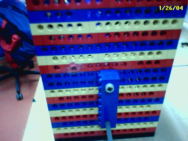
The Box:
The box is predominantly
made
out of legos and took a few iterations to get the dimensions right,
especially after changing the mechanism moving the jack. The box
is 21
layers of legos high and 16 fundamental LEGO units (FLUs) wide.
The
box had to be lengthened from the first trial and the position of the
light sensor and crank were changed.
The Cover:
The box top had a variety of covers that were experimented with.
Some
were made out of felt and paper with a line in the middle and small
cuts around it for the jack to pop out. These did not work too
well
because the jack would have difficulty getting out of the box and once
it did, the felt and paper pieces would cover his face.
Another idea for the cover was to have a thin and light piece of
cardboard cover the box and have an axle or two lift the cover right
before Jack would come out and slowly lower the cover when Jack was
done performing. The problem was finding the cardboard and room
for the motors.
I eventually
stumbled upon an empty tissue box in my room and found that this would
work perfectly. Small cuts were made around the clear plastic
opening
where tissues are dispensed to widen the area for the jack's head (he
has a pretty big head). The tissue box was cut and measured to
fit the
LEGO box. This was then covered with regular red paper. A
picture of the cuts to the plastic can be seen below in the section
entitled "Inside the Box".
The Light Sensor and Crank:
A light sensor for HandyBoards was embedded into one of the sides of
the box. A crank was made out of plates, some black connector
pegs, a
couple of small beams, an axle, a half axle for the handle, one
bushing, and a couple of pieces that looked like bushings. This
was
placed close to the light sensor so that each crank would completely
cover the light sensor. The first trial crank was made completely
out
of beams and did not work as well because light got in through the
holes and other shadows were cast. Plates worked a lot
better. Covering the light sensor with a thin piece of paper also
helped to
keep other shadows other than the crank or something up-close from
being
counted as a shadow.
The threshold for light was also increased to keep unwanted shadows
from interfering. (For more info on this, see the Code).
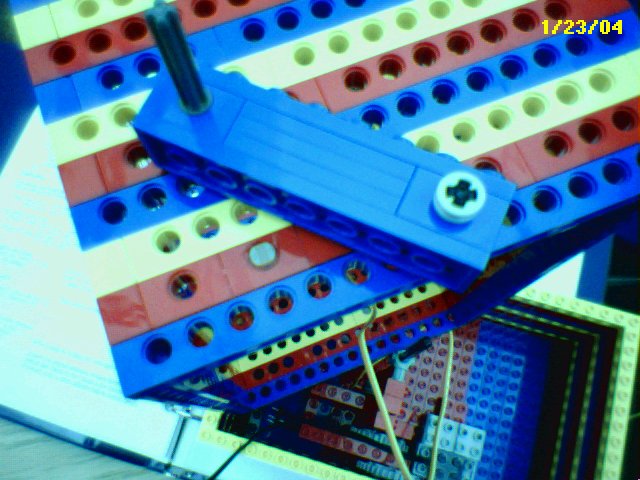
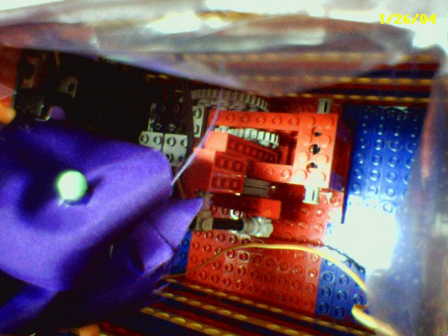
You cannot tell from this view, but the crank is not connected to
anything. It is just there to cast a shadow on the light
sensor. A view of the crank from the inside can be seen in the
third picture below in the section entitled "Inside the Box".
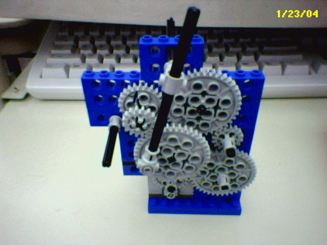
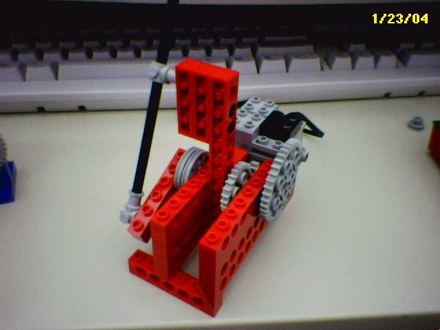
Gears and the Big Bob:
The first couple of iterations of the mechanism moving the jack were a
disaster. I started off with a leg-motion mechanism featured on
the
constructopedia. This was expanded with a complex gear train
which,
needless to say, did not work very well. It was still moving too
fast
and had occasional stalling. I feared using this would scare the
kids. Jack looked like he was having an epileptic fit.
However, this
was a more up and down motion typical of a jack-in-the-box.
Here is a picture of what it looked like:
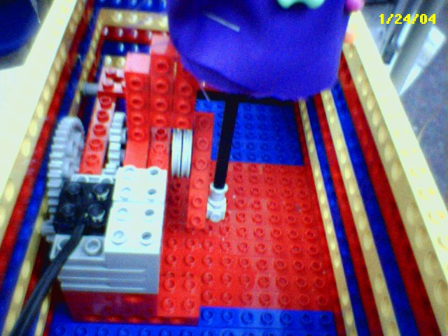
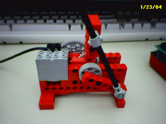
I later used the "big bob" design for motion modules which can be found
here.
The jack was able to move more smoothly even if it did not have the
sharper up and down motions of a regular jack-in-the-box. It
would go
in an ovalish shape. Since the box was a bit small, a smaller
axle and
smaller lego beam that is attached to the wheel were used so that the
jack wouldn't move too much. Below are some pictures of the big
bob
motion module before modifications.
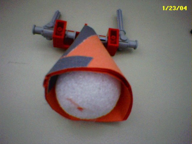
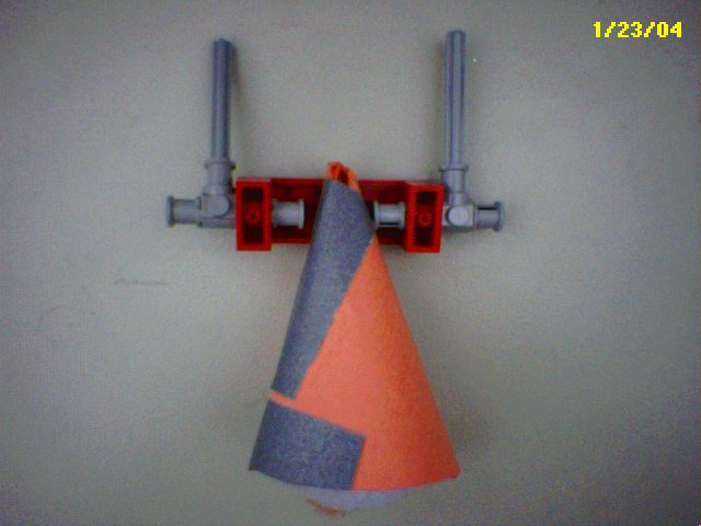
"Jack":

Jack was made out of two
styrofoam balls: one for the body and one for the head. His
attire is made out of whatever fabric that was available, including
some ribbon, beads, and puff balls. His hat was made out of
rolling pieces of ribbon into comes and hot gluing them to the
hat. The brim of the hat was made by curling the edges on top of
each other and hot gluing them to stay in place. His hair is made
out of pieces of colored feathers.
You may notice in other pictures, especially during the exhibition or
in the final jack-in-the-box that his nose is yellow. The red
nose was a bit too big and while trying to fix it...well, let's just
say the operation was unsuccessful. Fortunately, he got a newer,
smaller nose and is perfectly fine now.
Below are two pictures of Jack's body. One styrofoam ball is
covered in construction paper. Some lego pieces are attached to
this "body" and there are two axles for arms. Hands were added
later. An axle was glued onto the bottom of the styrofoam ball to
attach jack to the "big bob". A picture of that can be seen in
the next section below.
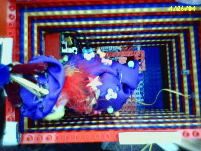
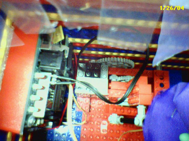
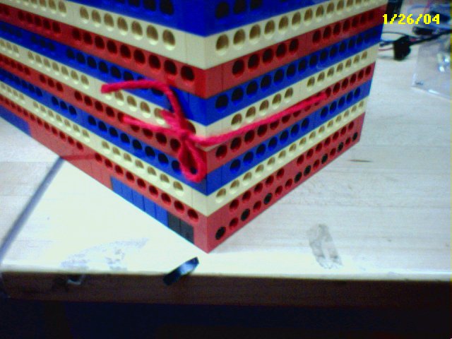
Inside the Box:
Here are some pictures of how things were arranged inside the box:
A string was tied to the side of the box to keep the HandyBoard in
place.
Next Page