
Circuits
Assignment: Circuits
- Assign: Friday 24 September
- Due: Friday 1 October
- Policy: Individual graded synthesis assignment
- Submit: Upload a PDF written on the cs240-circuits-worksheet.pdf submission sheet
- Reference:
Contents
Exercises
Please write your answers on the cs240-circuits-worksheet.pdf submission sheet to streamline the grading process. Submit your work by scanning a PDF of all worksheet pages (in order) and uploading it to Gradescope. Remember that this course uses your Gradescope account attached to your Wellesley email address (the variety that matches your username). You can merge accounts across multiple email addresses if helpful.
1. Karnaugh Map (10 points)
Consider the following Boolean Algebra expression which you saw earlier in your Entrance Gates assignment: $A’B’C’D’ + AB’C’ + AB’CD’ + ABD + A’B’CD’ + BC’D + A’$.
- Draw a truth table for the Boolean Algebra expression $A’B’C’D’ + AB’C’ + AB’CD’ + ABD + A’B’CD’ + BC’D + A’$. This is the same expression you saw earlier in your Entrance Gates assignment.
- Draw a Karnaugh map for the truth table above. Remember that the columns and rows of the table are structured by gray codes. Make sure to circle the map accordingly to indicate the minterms needed to derive a minimal sum of products.
- Using the Karnaugh map above, write down the minimal sum of products.
2. Encoder a.k.a. the Undecoder? (8 points)
Draw a circuit to implement a 4-to-2 encoder using gates. An encoder is the opposite of a decoder. It takes $2^n$ inputs and provides $n$ outputs. Here, $n = 2$. Assume exactly one of the inputs carries $1$ and all others carry $0$. The output should be an $n$-bit binary number giving the index of the input that is enabled. For example, if input $2$ (in the range $0..3$) is enabled and all others are disabled, the output should be $1$ $0$.
Label the inputs $In_0$, $In_1$, $In_2$, $In_3$ (representing the unencoded numbered options $0$ through $3$, respectively), with outputs $Out_0$ (representing the encoded number’s $2^0$’s place) and $Out_1$ (representing the encoded number’s $2^1$’s place).
3. Switching Network (8 points)
Draw a circuit to implement a switching network with two data inputs ($A$ and $B$), two data outputs ($C$ and $D$), and a control input ($S$). If $S = 1$, the network is in pass-through mode: $C = A$ and $D = B$. If $S = 0$, the network is in crossing mode: $C = B$, and $D = A$. Use the most reasonable combinational building blocks or gates. Label the inputs and outputs.
4. Flop-flip-flopping (10 points)
Note: this problem depends on the Sequential Logic topic, which may be covered after the assignment begins.
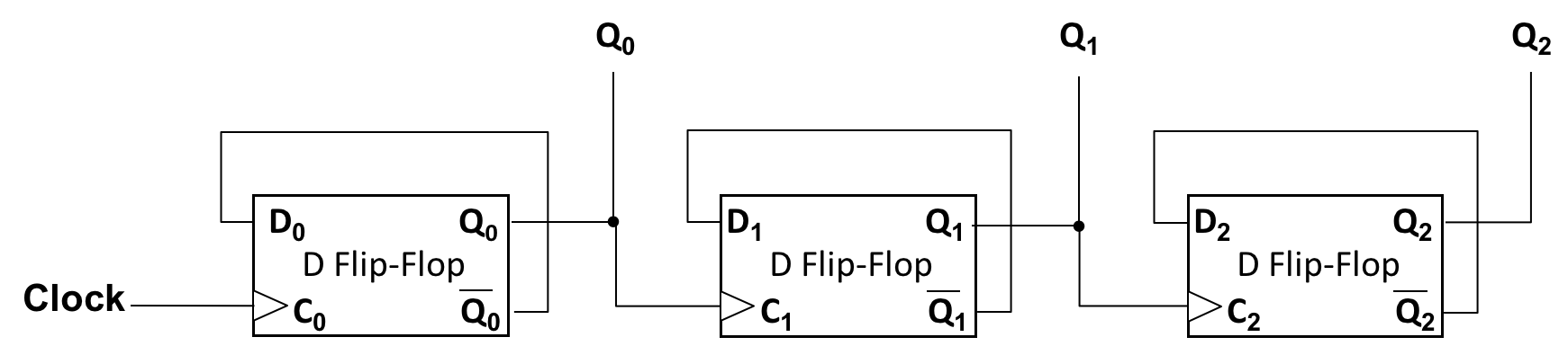
Consider the following circuit that uses falling-edge triggered D flip-flops.
| Cycles Completed | Q2 | Q1 | Q0 |
| 0 (initial state) | 0 | 0 | 0 |
| 1 | |||
| 2 | |||
| … | |||
| 10 |
Assume the Clock input, and outputs Q0, Q1, and Q2, are all initially 0. Draw waveforms for Clock, Q0, Q1, and Q2, showing at least ten Clock cycles. You do not need to turn in your waveform drawing, but it will help you reason about the circuit.
-
Write a table summarizing the values of Q0, Q1, and Q2 after each Clock cycle.
-
Briefly explain what this circuit does at a high level, treating the Q outputs together. A phrase to a couple sentences is enough.
5. Value Judgments (24 points)

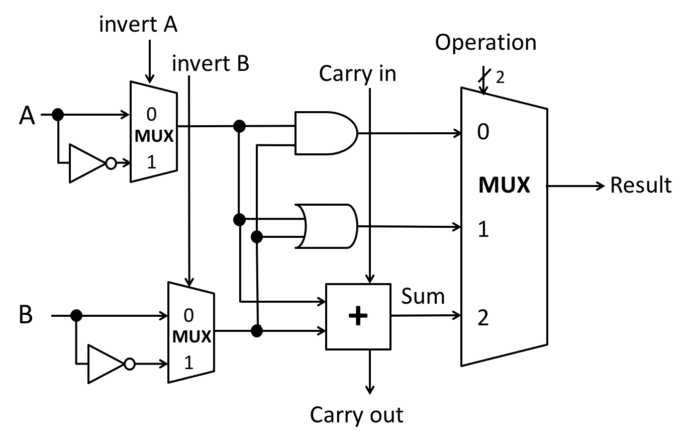
In class and lab we designed an $n$-bit ALU by connecting $n$ 1-bit ALUs. In these exercises, you will improve the 4-bit version of our design.
Summary of our ALU design:
- The
Carry outfrom each bit is wired to theCarry inof the next bit, if present. - The full $n$-bit ALU has 4 lines of control input:
Invert Acontrols theinvert Ainputs of all of the 1-bit ALUs.Negate Bcontrols:- the
invert Binputs of all of the 1-bit ALUs; and - the carry-in of the least significant bit ALU.
- the
- Two bits of
Operation IDcontrol theOperationinputs of all of the 1-bit ALUs.
Rules for extending the ALU:
- Any additional logic may connect to any existing wires in the ALU and add gates or other building blocks as needed.
- Minimize the number of gates or other building blocks you add.
- Choose the simplest option and clearly label new outputs.
- Feel free to draw answers for separate exercises on separate diagrams or to combine them in one diagram, as you wish.
Exercises:
-
[2 points] Design extra 1-bit outputs from the $n$-bit ALU for the four conditions codes (i)
Zero Flag, (ii)Sign Flag, (iii)Carry Flag, and (iv)Overflow Flag. Their definitions are given in the slides on ALUs. Using the provided sheet, draw and label the additional logic required for each condition code (flag), all on one ALU diagram. Feel free to reuse designs from your notes. - [6 points]
Describe the output of the ALU when
Invert A= 1,Negate B= 1, andOperation ID= 10.- Write your answer as an arithmetic or Boolean/bitwise expression
using $A$ and $B$, e.g.,
Result= $A \& B$ orResult= $\frac{2A}{B}$. - Your expression must use either arithmetic operators or Boolean/bitwise operators. You may not mix them.
- Write your answer as an arithmetic or Boolean/bitwise expression
using $A$ and $B$, e.g.,
-
[8 points] Consider a less-than check for two’s-complement operands that computes $A - B$ and returns a value based on the sign bit of the difference: 0 means $A \geq B$, 1 means $A < B$.
- [1 point] Give a pair of values, $A$ and $B$, where this approach correctly indicates $A < B$.
-
[1 point] Give a pair of values, $A$ and $B$, where this approach incorrectly indicates $A < B$, even though actually, $A \geq B$. Name the key effect that caused the answer to be incorrect.
- [6 points]
Redesign less-than using minimal additional logic to compute
the correct less-than result for all pairs of 4-bit
two’s-complement values. Provide a 1-bit output of the full
ALU in the style of the condition codes you implemented above,
yielding 1 if $A < B$ and 0 otherwise.
- Show how to control each of the 4 control lines of the full ALU:
Invert = ?,Negate B = ?,Operation = ??. - Using the provided sheet, draw and label your design.
- Show how to control each of the 4 control lines of the full ALU:
- [5 points]
Design a 1-bit equality test output for the ALU using minimal
additional logic (but no additional XOR gates). Given inputs $A$ and
$B$, this output wire should carry 1 if $A = B$ and 0 otherwise.
- Show how to control each of the 4 control lines of the full ALU.
- Using the provided sheet, draw and label your design.
- [3 points] Consider the similarities and differences in the workings of your designs for less-than and equals. Does the problem we encountered with less-than matter in your design of equality logic? Briefly explain why or why not.
Submission
Please write your answers on the cs240-circuits-worksheet.pdf submission sheet to streamline the grading process. Submit your work by scanning a PDF of all worksheet pages (in order) and uploading it to Gradescope. Remember that this course uses your Gradescope account attached to your Wellesley email address (the variety that matches your username). You can merge accounts across multiple email addresses if helpful.