Entity Relationships Diagrams
ER diagrams are a useful way to picture the entities that we are storing in our database (e.g. people, movies, pets, owners, albums, tracks) and the relationships among them.
There are some excellent readings at the end of this introduction.
- Entity-Relationship Model
- Conceptual Modeling
- Building Blocks
- Entity Sets
- Relationship Sets
- One-to-one relationships
- Converting ER to DDL
- Converting Entity Sets
- Converting Relationship Sets:
- Relationship Attributes
- Enhancements
- Participation Constraints
- ISA Hierarchies
- Syntax Rules
- Drawing Software
- Readings
Entity-Relationship Model
- Goal is to accurately model the "world" that we are trying to capture in our database.
- Pictorial tool.
- Eventually "translated" into SQL DDL (table definitions). This translation can be rough sometimes.
Here's an ER diagram for the WMDB

Conceptual Modeling
Entities are the objects or nouns we are interested in.
Relationships are the connections among them. Sometimes, they correspond to verbs.
No standard drawing, although some are very common. We will pick one style and stick to it.
Afterwards, convert ER diagrams to CREATE TABLE statements
Building Blocks
Some terminology:
- Entities: like objects. Entity Types (Entity Sets) are a little like classes in object-oriented programming. Pictured with a box.
- Attributes: properties or characteristics of entity types. Pictured as an oval attached to the box.
- Domains: the possible values of an attribute. E.g. integer or string. Not pictured.
- Schema: The collection of entity type name, attributes, whether they are set-valued, and all that. Not pictured.
Keys
Entity sets often have keys:
- a set of attributes that uniquely specifies an entity. E.g. SSN, or (FirstName,LastName,ClassYear)
- no subset of those attributes works
Other observations:
- The key should be unique by definition, not by happenstance. A person's name could be unique at Wellesley, until someone else with that name matriculates.
- There may be more than one key. Can you think of two or more keys for a Wellesley student?
- The database should enforce the key constraint.
Pictured by underlining the key attribute(s)
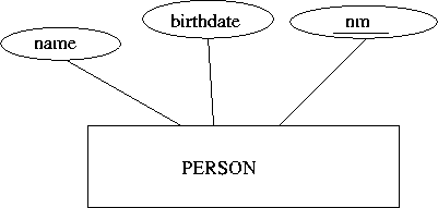
Entity Sets
Entities are where the "things" that we are keeping track of. This is usually pretty intuitive. A database for a car dealership needs to keep track of cars, customers, sales agents, ...
Pictured with a box, with attached ovals for attributes:
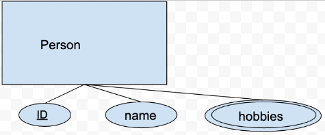
Attributes can sometimes be be set valued. For example, a "genre" field added to our WMDB might be set-valued: Mystery, Drama, Comedy, Horror, etc. A movie might fit in more than one genre. Pictured with a double oval. Here's an example of a person table where a person can have some hobbies.
Relationship Sets
- Relationships: connections among entities. Binary, Ternary, more
- Entity sets play roles in relationship sets.
- Relationship sets connect entity sets.
- Relationship sets don't connect relationship sets.
Most relationships are binary: For example, an owner owns a pet. owns(oid,pid). That's a connection between two things.
Some relationships are ternary: For example, Sirius gives Harry a Firebolt: gives(sirius, harry, firebolt). That's a connection among three things.
We can even have relationships among four or more things, though they are increasingly rare.
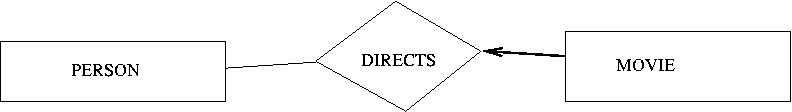
Here's an example of the directs relationship, a binary relationship.
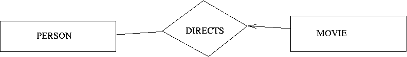
In our world, a movie only has 1 director, so this is a one-to-many relationship between Movies and People. Therefore, we draw an arrow from Movie to Directs, because Movie is a key of the relationship set. This is the key constraint
What about a many-to-many relationship? How about movies and people?
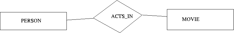
Here, we have to have the intermediate table representing the relationship. Essentially, the relationship is two one-to-many relationships.
Relationships can be Ternary as well as Binary, though this is less common.
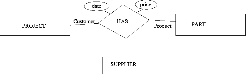
Here's an example. The idea is that there are generic parts
in the
world, such as 2-inch #6 bolts or AA batteries. There are
suppliers,
such as Eveready, Duracell and others. There are
projects
that need parts like bolts and batteries. If the project
leader buys a particular product from a particular supplier for a given
price on a given day, that event creates a relationship among three
entities.
One-to-one relationships
Many-to-one and many-to-many relationships are common, but it's rare
for a relational database to store a one-to-one relationship. That's
because most of the time, the different pieces of information for an
entity would simply be all together in one row of one table. That is,
rather than have a separate table for birthdays, with a key of the
nm and a 1-1 relationshipship with the person table, we just put
the birthdate in the person table.
But sometimes data are stored in the separate tables. Here are a couple of reasons:
- The data is bulky and rarely needed. For example, each person in the
WMDB might have a "biography": a long piece of text that we often
don't need. So we could have a separate table,
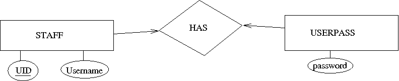
biographywith thenmbeing the primary key, and a 1-1 relationship with thepersontable. - The data has different permissions. (MySQL defines permissions on a
per-table basis.) For example, if you want the
stafftable to be readable by all, but thepasswordtable to only be readable by select people, then you would define theuserpasstable to be separate, but withuidas the key, and a 1-1 relationship with thestafftable. Pictured below. - The data is another entity. For example, we might have a 1-1
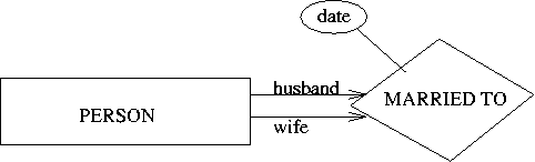
relationship between people called
married_to. Pictured below.
Converting ER to DDL
While the main goal of an ER diagram is to picture the relationships, we often use the diagram to guide our definitions of the tables. Here's how it might work.
Converting Entity Sets
- entity set → relation/table
- attribute → attribute/column
- But, set-valued attributes may require additional tables to avoid redundancy.
create table person(
nm int,
name varchar(30),
birthdate date,
primary key (nm));
-- as of MySQL 5, "release" is a reserved word;
-- have to put the field name in backquotes.
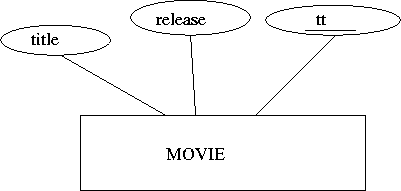
create table movie(
tt int primary key,
title varchar(50),
`release` char(4));A set-valued attribute could be turned into a column with a set of possible values, or a 1:N mapping with a table of possible values. Here's an example, using "hobbies", which are stored in a separate table with a foreign key to the person table.
| ID | Name |
|---|---|
| 34 | Homer |
| ID | Hobby |
|---|---|
| 34 | TV |
| 34 | beer |
| 34 | doughnuts |
Converting Relationship Sets:
- Relationship set → relation/table
- key is usually union of keys of roles
Here's a repeat of the directs relationship, along with the SQL.
Here's that diagram in DDL:
create table movie(
     tt        int,
     title     varchar(50),
     `release` char(4),
     director  int,
     primary key (tt),
     foreign key (director) references person(nm)
     on delete set null on update cascade);
Relationship Attributes
A relationship can have attributes as well. Here, we record the date that a student declared a particular major.
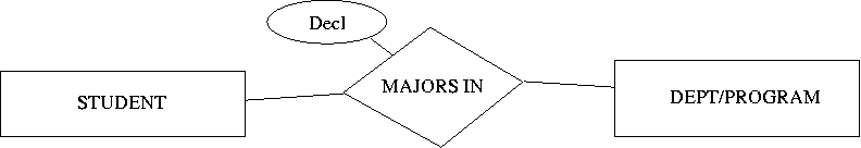
create table majorsin(
    sid int,
    did int,
    decl date,
    primary key (sid,did),
    foreign key (sid) references student(sid)
    foreign key (did) references department(did));
Roles can be labeled. Here's an example.
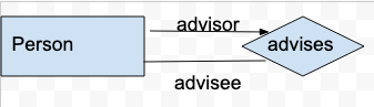
The roles usually become column names:
create table advise(
    advisor int,
    advisee int,
    foreign key (advisor) references person(ssn),
    foreign key (advisee) references person(ssn),
    unique (advisor));
Enhancements
The preceding diagram rules are the basics. There are two enhancements that we will add: participation constraints and ISA hierarchies.
Participation Constraints
If every X must have a Y, this is called a participation constraint. Examples:
- Every Movie must have a director
- Every Prof must have a Dept
- Every Dept must have a Chair
In an ER diagram, this is represented with a thick line or (sometimes) a double line. Here, if we decide that every movie must have a director, we can draw it like this:
In SQL, we can enforce a participation constraint with a "not null" and "foreign key" constraint. For example:
drop table if exists movie;

create table movie(
     tt        int,
     title     varchar(50),
     `release` char(4),
     director  int not null,
     primary key (tt),
     foreign key (director) references person(nm));
However, this can be annoying:
- What if the value is unknown? You can't enter the data you do not know.
- What if the value is temporarily vacant? For example, a department doesn't have a chair for some interregnum period.
ISA Hierarchies
Very often in the world, there are entities that have subtypes. The subtypes have all the attributes of the supertype, but maybe with some extra attributes or different relationships.
This is pronounced as if it were the two-word phrase "is a" smushed together. So a "cat is a mammal" becomes "cat ISA mammal".
- An Employee ISA Person, as are Professors, Staff, and Students.
- A Professor ISA Employee, as is a Staff worker.
- What about contract employees, hourly, salaried, etc.?
Pictured using triangles:
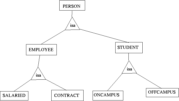
In implementation as DDL, there are two choices:
- the subtypes could all be combined into one large table, with NULL
columns for the irrelevant columns (so the
dormcolumn is NULL for an off-campus student). Or, - the subtypes can be put it different tables that are dynamically combined using JOIN and a shared key.
The tradeoffs are between the time cost of joins and the space cost of storing lots of NULLs. We will not worry excessively about this. Think about it, make your best guess, and go ahead.
Syntax Rules
That's it.
Please remember the following syntax rules for ER diagrams, the way we're doing them:
- relationship lines connect boxes to diamonds; a box is never directly connected to another box
- arrowheads, if any, go on the diamond, not on the box
- In a one-to-many relationship, the arrow goes from the many towards the one. E.g. movie has just one director, but a person can direct more than one movie, so the arrow goes from movie to director.
- attributes are circled.
- attributes that are (part of) the key are underlined.
- Every entity set should have a key
- Use ISA for inheritance of attributes
- something that is a key to an entity set should not also be an attribute of another: instead, there's a relationship
A few more rules to keep in mind when converting ER diagrams to DDL:
- Not every diamond becomes a table. Some data can be "absorbed" into another table. (E.g. director is absorbed into the "movie" table)
- Many-to-many relationships may result in an extra table.
Drawing Software
You can, of course, draw these diagrams with pencil and paper and either hand those in or scan them and email them to me. You can also create electronic drawings using Fireworks, Photoshop, the GIMP, or any of many other drawing applications.
Most students use Google Drawings, and that's fine.
Readings
Some sources are:
- Professor Jessica Lin's slides or Professor Jessica Lin's slides (local). Students have found these pretty helpful.
- Entity-Relationship Model, Wikipedia article. The first part of this is too abstract for words, but the section entitled "The building blocks: entities, relationships, and attributes" is good, so read that section, at least. The section on Diagramming Conventions is also good; we'll use Chen's notation.
- Ramakrishnan and Gerkhe. These are slides based on a chapter from an excellent book that I used to use for this course. This is the most important one to read, and uses the terminology and diagram conventions that we will use. However, they get into some esoteric aspects of ER diagrams, so you can ignore Weak Entities and Aggregation. ISA is important though, so please notice that.
- Introduction to ER modeling. This is long and uses different notation and diagram conventions than we will use, but is useful if you'd like a bit more explanation.