CS307: Building Composite Objects
Plan
- Quick reminder: affine transformations (position, rotation, scale)
- Composite objects in Three.js
- Nested frames: Explore the cone, fence, curved fence, and leg demos
- Exercise: Luxo mom and junior
- Recap and questions: representing transformations as matrix multiplications
- The TeddyBear demo
- HWK2: Clown
- (if time) Exercise: Scale of Justice
Recap of Affine Transformations
We can use the following operations (affine transformations) to place things in our scenes:
- translation:
obj.position.set(px,py,pz);
obj.position.x = px;
obj.position.y = py;
obj.position.z = pz;
- rotation:
obj.rotation.set(rx,ry,rz);
obj.rotation.x = Math.PI/2;
obj.rotation.y = Math.PI/3;
obj.rotation.z = Math.PI/4;
- scale:
obj.scale.set(sx,sy,sz);
obj.scale.x = sx;
obj.scale.y = sy;
obj.scale.z = sz;
You're now learning how to use these same methods, plus some new ones, to place objects inside other objects, nested as deeply as we want.
Composite Objects in Three.js
We can build a composite object using the THREE.Object3D class
and .add() method
- in its own frame (coordinate system and origin)
- that you can place independently of other composite objects
- that you can rotate around different points
Explore the Cone Rotation Example
You looked at this for the reading. Now let's look at it carefully
together. Here's a picture:
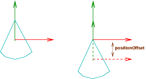
positionOffset. Initially, the
offset is zero. We can rotate the cone around the origin
of either frame.
Here it is in action. It demonstrates rotating around a point other than the origin of the geometry.
Fence Examples
The fence examples demonstrate cloning and repeated transformations. These transformations will accumulate from one picket to the next.
The Leg Example
The leg demo shows deeply nested frames, but each nesting is just like the Cone demo. First, here are two pictures from the reading:
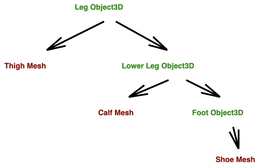
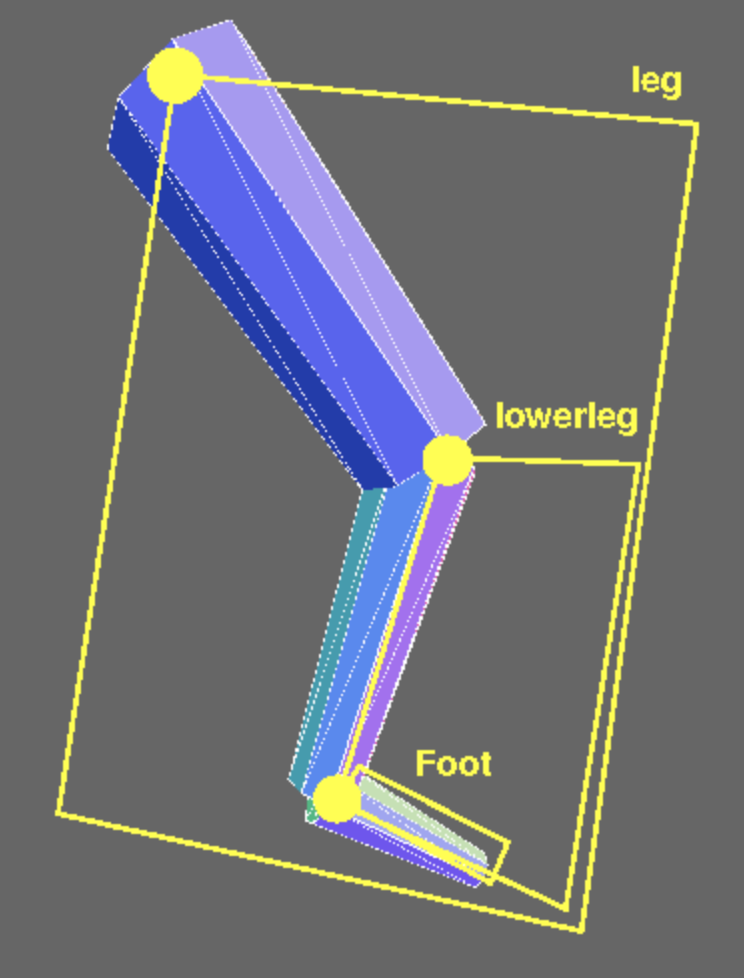
The leg scene contains objects nested within objects. On the left, the instances
of Mesh are in brown, and the instances of Object3D
are in green. On the right, the three Object3D frames are
outlined in yellow.
The leg and lowerleg objects each contain a mesh
and a sub-object. In each case:
- the mesh is a cylinder of some length L
- the mesh is placed at y = -L/2
- the sub-object is placed at y = -L (the far end of the mesh)
- the origin for the object is at the near end of the mesh
The creation of the foot object is a slight variation on the
above structure. This diagram also includes the rotations
that can be adjusted with the GUI:
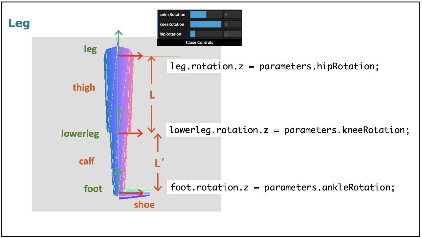
Here's the final demo: Leg
This sequence of slides slowly builds up the elements of the leg code.
Exercise: Luxo Mom and Junior
This exercise highlights the idea of creating an instance of the
THREE.Object3D class to store a set of THREE.Mesh
objects that represent the parts of a composite object. The
THREE.Object3D container object can then be placed anywhere
in a scene using the affine transformations listed above.
To begin, open a copy of the luxo-start.html
code file in an editor. The file contains a function named
luxo() that creates a simple luxo lamp and adds it to a
scene. A green rug is also added to the scene.
Modify the code to do the following:
- Modify the
luxo()function to- create an instance of a
THREE.Object3Dto serve as a container object - add all the meshes to this container object (instead of the scene)
- return the container object
- create an instance of a
- Replace the single call to the
luxo()function with code to create two luxo lamps, mom and junior, where- mom is placed at location
(60,0,60)in the scene's coordinate frame - junior is half the size of mom, placed at scene location
(160,0,60), and rotated so that he is facing mom
- mom is placed at location
Your final solution should look something like this:
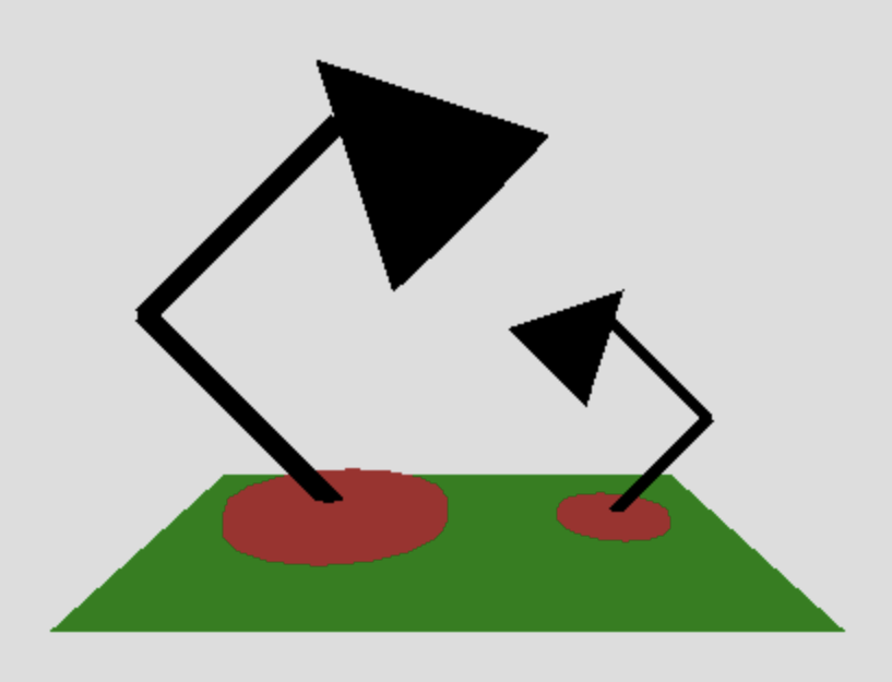
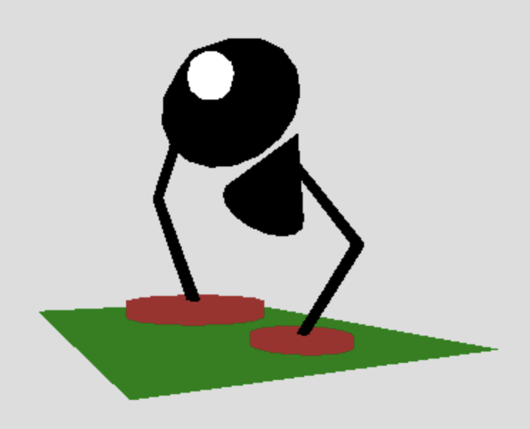
Here is a solution: luxo-family.html
Affine Math
- Translation, rotation and scale are kinds of affine transformations.
- An affine transformation maps line segments onto line segments and triangles onto triangles. That's good for Computer Graphics.
- An affine transformation in 3D using homogeneous coordinates can be represented with a 4x4 matrix.
- Homogeneous coordinates add a fourth component, $w$, to all
vectors and points — we'll assume for now that $w=1$ (points):
\(
\newcommand{\vecIV}[4]{\left[\begin{array}{c} #1\\#2\\#3\\#4 \end{array}\right]}
\)
- Translation: \[ \vecIV{x+\Delta x}{y+\Delta y}{z+\Delta z}{w} = \left[ \begin{array}{rrrr} 1 & 0 & 0 & \Delta x \\ 0 & 1 & 0 & \Delta y \\ 0 & 0 & 1 & \Delta z \\ 0 & 0 & 0 & 1 \end{array} \right] \vecIV{x}{y}{z}{w} \]
- Rotation (around Z in the example below): \[ \vecIV{x'}{y'}{z}{w} = \left[ \begin{array}{rrrr} \cos\theta & -\sin\theta & 0 & 0 \\ \sin\theta & \cos\theta & 0 & 0 \\ 0 & 0 & 1 & 0 \\ 0 & 0 & 0 & 1 \end{array} \right] \vecIV{x}{y}{z}{w} \]
- Scaling: \[ \vecIV{s_x x}{s_y y}{s_z z}{w} = \left[ \begin{array}{rrrr} s_x & 0 & 0 & 0 \\ 0 & s_y & 0 & 0 \\ 0 & 0 & s_z & 0 \\ 0 & 0 & 0 & 1 \end{array} \right] \vecIV{x}{y}{z}{w} \]
Associativity of Matrix Multiplication
The naive way to apply multiple transformations is to perform a separate matrix multiplication for each transformation. We'll use T, R and S to stand for translate, rotate and scale. Here each vertex gets 7 transformations: \[ v' = S(R_2(T_4(T_3(T_2(R_1(T_1( v))))))) \]
The clever way is like this, precomputing the 7 transformations as one: \[ C = (SR_2T_4T_3T_2R_1T_1) \\ v' = C v \]
This is worthwhile when the number of vertices is very large.
By making all of the operations be matrix multiplications, we can represent and store the collective effect of a set of transformations, at significant savings in time:
- Doing N transformations on M vertices the naive way takes 16NM multiplications
- Doing N transformations on M vertices the clever way takes 64N + 16M multiplications
This can be a huge savings when M is large, which it often is. Think about the number of vertices in the teddy bear!
Also, the graphics card only has to store one Current Transformation Matrix (the CTM), not N, so there's a space advantage as well.
Finally, there's the convenience of being able to save and restore the CTM just by pushing it onto and popping it off of a stack.
Teddy Bear Demo
The full TeddyBear demo uses many nested frames.
To see how these nested frames are implemented, we'll begin with this
slightly stream-lined code for Teddy's Head
that just creates a THREE.Object3D object for the bear's head and adds
it directly to the scene, with the origin of the head object coinciding with the origin
of the scene's coordinate system.
The creation of the Teddy Bear's body also demonstrates multiple rotations. For example, to get a tube in the orientation we want for the teddy bear's leg:
- The
createLimb()function returns an object that contains a cylinder mesh with the origin at the center of the top of the cylinder and the -Y axis running down the center of the cylinder. - We use a negative rotation around the X axis to lift the legs up a bit.
- We use a positive rotation around the Z axis to spread them out.
Exercise: Scale of Justice
Suppose we want to create a rendering of the Scale of Justice:

Our rendering won't be nearly as ornate, but we'd like to approach the solution in a way that would facilitate some added embellishments.
Your starting point is this scale-start.html code file that just creates a base and pole for the scale. This initial file contains code for:
- an object named
paramsthat contains two parameters,sizeandangle, that can be controlled with the GUI - an array named
materialsthat contains black and red materials - a function
createCone()that creates and returns a "cone object" with its origin at the top of the cone - a partial definition of a function
createScale()that creates and returns a "scale object" — where is the origin of this container object?
This file also contains code for the GUI controls and sets up a bounding box that is suitable for the scene.
Your task is to:
- complete the
createBeam()function that creates and returns a "beam object" that contains a cylindrical beam and two cones to portray the rest of the scale — what is a convenient origin for this container object? - add code to the
createScale()function to callcreateBeam()and add the beam to the scale
A couple tips on completing CreateBeam():
- this function has two inputs,
sizeandangle, wheresizeis the length of the beam andanglespecifies the orientation of the beam, measured from the horizontal axis (in the GUI, this angle is initially 0) - place two cone objects at the tips of the beams, taking into account the
sizeandangleof the beam
Why might it be advantageous to divide the creation of the scale into
multiple parts, with separate container objects (i.e. instances of THREE.Object3D)
for some parts?
Your final solution might look something like this:
scale.html
(adjust the GUI controls to change the size and
orientation of the beam)
(Optional)
If you have time, add some embellishments or improvements to
createCone() or createBeam(), such as those shown in this
snapshot:

Summary and Preparation for Next Time
- Graphical items can be a hierarchy (graph) of meshes and sub-items.
- Each sub-item can have its own local coordinate system for placing sub-parts.
- Affine tranformations (translate, rotate and scale) are our tools to place and arrange parts.
Next time, we'll look at the Camera API and the mathematics of projection, which will also involve matrices. To prepare:
- Reading for Thursday: Synthetic Camera API
- Submit Sakai Quiz by Wednesday evening at 9:00 pm EST — you'll have an hour to complete the quiz, which is "open book/notes"
Work on HWK2 with your partner (due Friday at 11:00 pm EST)