CS307: Texture Mapping 3: Texture & Lights, Textured 3D Shapes, and More
Plan
- Texture, surface color, and lights
- Nearest & linear filters
- Mapping textures onto curved 3D surfaces
- Exercise: Decorate a cake
- Exercise: Build a globe
- Advanced techniques: bump, normal, and environment maps
Texture, Surface Color, and Lights
Texture mapping adds a pattern of varying lightness or color to a surface.
- What if the surface itself also has a color with hue?
- How does surface texture mapping interact with light sources in the scene?
The texture is multiplied by the color of the surface. For a single surface location:
- let (RP, GP, BP) refer to the RGB color specified for the Phong material
- let (RT, GT, BT) refer to the RGB color of the texture at this location
- the resulting color is then given by (RP x RT, GP x GT, BP x BT)
In the pyramid scene, the RGB values for the texture range from 0 to 255, and we think of the RGB values for the surface color as ranging from 0 to 1, so multiplication of the texture color by the surface color yields smaller values for RGB, corresponding to darker surfaces.
If any of the R, G, or B values are 0 then the surface will not reflect any of that color component, so the corresponding color component in the image will be 0!
We can always "brighten up" surfaces in the scene by increasing the intensity of the light sources!
In the following demo, some red is added to the pyramid texture, yielding the color pattern shown on the plane in the upper right. The pyramid surfaces use Phong material with three different surface colors that have the effect of "toning down" the red, green, or blue components, respectively.
texture-mapped pyramid with surface color and lighting
The above example uses white ambient light. Suppose we change the ambient light to have a strong blue component?
texture-mapped pyramid with blue-dominated ambient light
Nearest and Linear Filters
When mapping texture onto a triangular face during the rendering process, Three.js:
- first determines which texture coordinates to use for each pixel touched by the triangular face
- then determines which texture color to use for each pixel, based on the texels around the computed texture coordinates
Pixels in the triangular face could be larger or smaller than the corresponding texels:
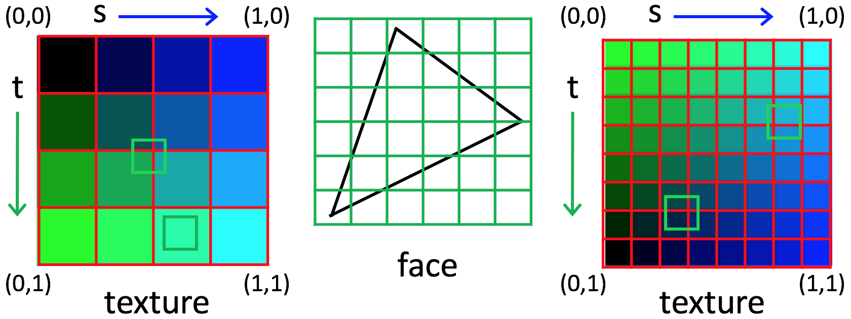
The minFilter property of a THREE.Texture object controls how the
texture color is determined for the scenario on the left, and the magFilter property
specifies what to do for the scenario on the right. Two common options for both are
THREE.NearestFilter (select the color of the nearest texel) and
THREE.LinearFilter (linearly interpolate between the colors
of the four nearest texels).
Summary:
- magnification: 1 texel &Rarr many pixels; 1 pixel &Rarr part of a texel. Should the pixels all be uniform (nearest) or gradually transition to the next texel (linear)
- minification: 1 pixel &Rarr many texels. Should the pixel color be drawn from one texel (nearest) or smoothly interpolate (linear)
texture-mapped pyramid with choice of linear/nearest interpolation of texture color
In practice, minFilter rarely matters.
Mapping Textures onto Curved 3D Surfaces
In Three.js, textures can be mapped onto curved objects (e.g. sphere, cone, cylinder, or torus)
in the same way that they're mapped onto flat surfaces, by setting the map property
for the material to a THREE.Texture object.
Exercise: Decorate a cake
The goal of this exercise is to create a decorated cake, something like this:
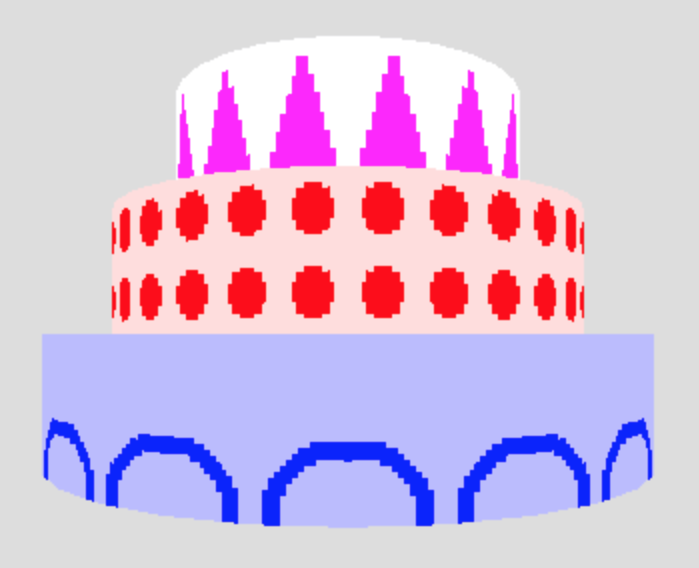
Begin with this cake-start.html code file, which we'll examine in detail. The starting code creates a single cylinder mapped with a texture pattern consisting of a blue dot on a white background, repeated 15 times around the cylinder.
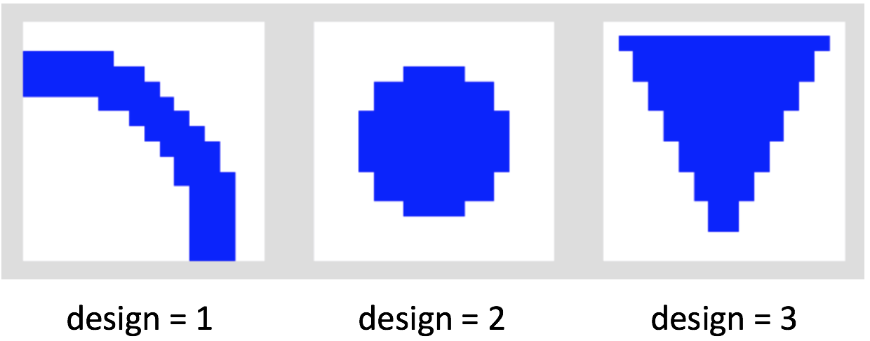
The makeTexture() function has several inputs — the first is an integer from
1 to 3 specifying which of three design patterns to use. The three designs are shown below:
Modify the code to create three stacked cylinders, each with a different color, texture pattern, and repetition method, similar to the decorated cake pictured above. You'll need to:
- Create two cylinders, adjusting the radius, position, color,
and texture, including different calls
to
makeTexture() - add them each to the scene.
Your solution might look like this cake.html
Observe the patterns displayed on the top and bottom surfaces of the cylinders.
How does Three.js map the texture onto these surfaces?
How are locations on the surfaces of the cylinders related to the
(s,t) texture coordinates?
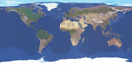
Exercise: Build a globe
In this exercise, you'll map an image of the world onto a sphere, to create a globe.
First, download this globe-start.html code file and image file to your Desktop.
Start a local server on your computer by following these steps:
- Start a terminal window
-
cdto the directory that has your downloaded HTML and image files in it, in this casecd ~/Desktop - Start a web server on port 8000 (by default) using Python:
python -m SimpleHTTPServer - Go to your web browser and enter the following URL (replace
foo.htmlwith the name of your HTML file on your local machine):http://localhost:8000/foo.html
Complete the makeGlobe() function to create a world
globe.
Your solution might look like this globe.html
Suppose we instead map the following image onto the sphere:
Note that the top and side lines of the grid are a lighter shade of gray. How do you think the result would appear?
View this result, rotating the sphere to see the
top, bottom, and sides. Where are the (s,t) texture coordinates equal to 0?
Advanced Methods
In his book on Three.js, Jos Dirksen presents some fun demonstrations of texture mapping. We'll explore some of these in class:
Other demos can be found at the Three.js website
Bump Maps
Consider this example of the use of a bump map: 08-bump-map.html
A bump map enables us to simulate bumps and wrinkles on an object surface. Traditionally, bump maps have been incorporated as follows:
- the bump map is used to perturb the normal vector at each calculated point
- the perturbed normal vectors are used during lighting calculations (e.g. application of the Phong model)
The underlying surface geometry is not changed in this case.
In Three.js, the bump map is a grayscale image, and the intensity values in this image are first used to displace each surface point slightly. The modified surface points are then used to calculate the normal vectors for the lighting calculations.
Here's the stone texture and bump map:


Here's the code:
var sphere2 = createMesh(new THREE.CubeGeometry(15, 15, 2),
                         "stone.jpg", "stone-bump.jpg");
The material includes a bump map:
function createMesh(geom, imageFile, bump) {
    var texture = THREE.ImageUtils.loadTexture("../assets/textures/general/" + imageFile)
    geom.computeVertexNormals();
    var mat = new THREE.MeshPhongMaterial();
    mat.map = texture;

    if (bump) {
        var bump = THREE.ImageUtils.loadTexture("../assets/textures/general/" + bump)
        mat.bumpMap = bump;
        mat.bumpScale = 0.2;
        console.log('d');
    }

    var mesh = new THREE.Mesh(geom, mat);
    return mesh;
}
Normal Maps
Consider this example of the use of a normal map: 09-normal-map.html
The normal map directly specifies the normal vector to use for the lighting calculations
(e.g. in the Phong model) at each location. It can be stored as an RGB image, where the three values
at each location represent the (X,Y,Z) coordinates of the surface normal.
Here are the plaster maps:


Here's the code:
var sphere2 = createMesh(new THREE.CubeGeometry(15, 15, 15),
                         "plaster.jpg", "plaster-normal.jpg");
The material includes a normal map:
function createMesh(geom, imageFile, normal) {

    if (normal) {
        var t = THREE.ImageUtils.loadTexture("../assets/textures/general/" + imageFile);
        var m = THREE.ImageUtils.loadTexture("../assets/textures/general/" + normal);
        var mat2 = new THREE.MeshPhongMaterial({
            map: t,
            normalMap: m
        });
        var mesh = new THREE.Mesh(geom, mat2);
        return mesh;
    } else { ... }

    return mesh;
}
Environment Maps
Consider this example of the use of an environment map (from the Second Edition of the Dirksen book): 05-env-map-static.html
Calculating real reflections of a surrounding environment from a shiny surface is very CPU-intensive, usually requiring ray tracing. Environment maps enable us to fake the creation of these reflections with far less computation.
To incorporate an environment map, a "CubeMap" object is first created from six images that represent the scenes that would be viewed in six cardinal directions from a central origin.
For the above Dirksen demo, these are the six images, with names indicating the
associated axis and direction of view:
posx: posy: posz:  negx:
negx: 
 negy:
negy: 
 negz:
negz: 
A large box is then created with the CubeMap rendered on the inside of the box. This gives the impression of being surrounded by an open scene, when in reality, the six image textures are rendered on the inside of a box and viewed from inside the box.
The CubeMap object can can also be applied as a texture, mapped onto the surfaces of a shiny object placed inside the box. This combination of the surrounding box and inner objects gives the (false) impression of objects reflecting the environment!
If you're interested in the details, have a look at the source code for this example.