Reading: Texture Mapping
Texture Coordinates
Suppose you want to repeat a texture pattern across a surface, or use only part of the image texture, or display the texture upside-down or mirror-reversed? To do these things, we need to introduce texture coordinates, sometimes called texture parameters.
A texture is an array of pixels, such as an image, and the
coordinates of locations within a texture array are represented
conceptually using a coordinate system that ranges from 0 to 1
in the horizontal and vertical directions. Typically, s
and t are used to denote the horizontal and vertical
coordinates, although (u,v) is also used (as in
Three.js).
The diagram below shows two sample images that might be used for texture mapping, showing the texture coordinates:
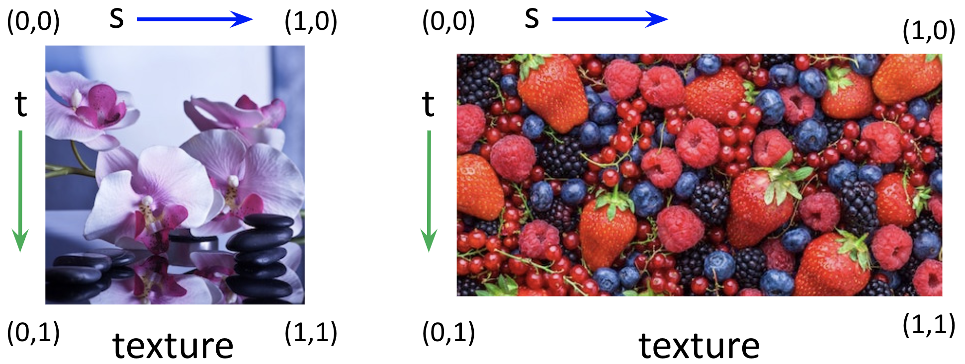
Regardless of the aspect ratio of the image dimensions, the
texture coordinates range from (0,0) in the upper
left corner to (1,1) in the lower right corner.
Three.js has a default strategy for mapping from the above texture
coordinates to the triangular faces of a built-in geometry, but often
we want to control this mapping more carefully. We do this by
specifying a pair of texture coordinates (s,t) for
each vertex of the geometry. For geometries that we create from
scratch, this step is essential.
The coordinates are sometimes called (s,t) and
sometimes (u,v). They are called (u,v) in
the code we used in
constructing custom
geometry
and THREE.js
custom geometry. Please look at both of those links and remind
yourself of the (x,y,z) and see how
the (u,v) coordinates are handled in the same way.
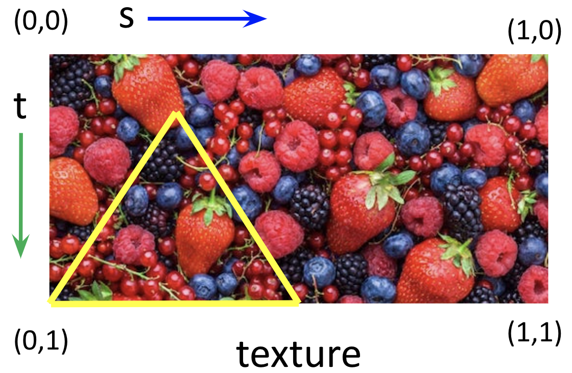
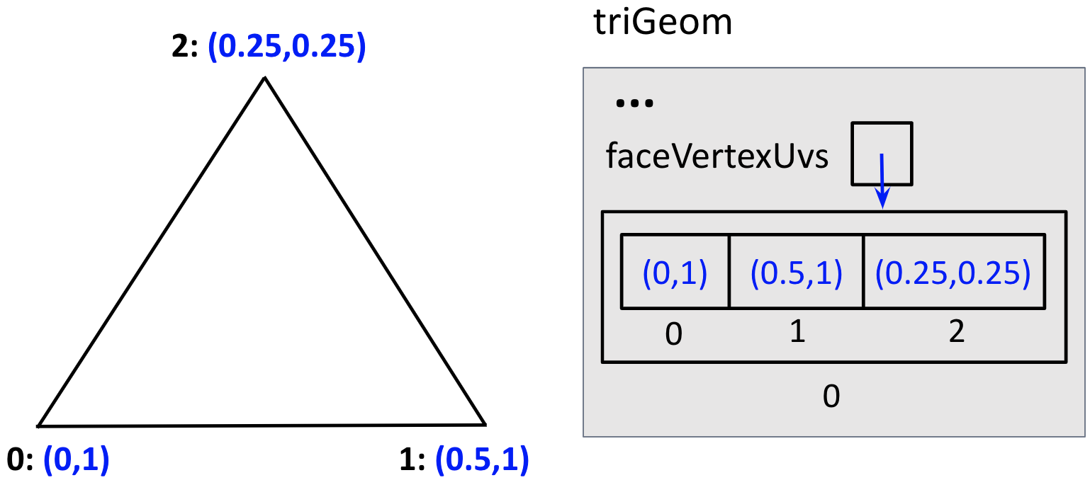
In the next demo, a geometry is created that has a single triangular face, with a triangular portion of the above berries image texture-mapped onto the triangle:
Note that the portion of the image that is mapped into the triangle is taken from the bottom-left portion of the berries image. How was this specified?
In class, we'll discuss how texture coordinates are represented.
Note that Three.js flips images upside-down when loading,
but setting the flipY property for the texture
to false reverses this change.
The next example maps four different images onto the four triangular
faces of a tetrahedron geometry created from scratch. The
addTextureCoords() function adds texture
coordinates for each of the four faces, using a helper
function faceCoords() that adds these
coordinates for a single face to an array named
UVs being constructed for the
faceVertexUvs property described above.
Be sure to examine the source code for this demo:
tetrahedron with four images mapped onto its faces
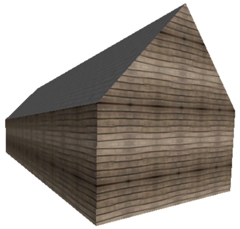
Repeating Textures
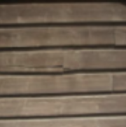
Suppose we want to create the appearance of a natural repetitive texture, such as that shown on the sides of the barn below. We can achieve this effect by tiling the surface with multiple copies of a small snippet of texture, like that shown to the right of the barn.
In Three.js, there are at least two ways to repeat a texture on an object surface:
- set the
repeatproperty of aTHREE.Textureobject to indicate the number of times to repeat the texture in the horizontal and vertical directions - set the texture coordinates
sandtassociated with verticies in the Geometry to have values larger than 1
In both cases, we also need to specify how the texture is wrapped horizontally and vertically.
In the following demo, the floral image is again mapped onto a plane, but repeated four times in the horizontal direction and twice in the vertical direction:
plane with repeated flower images
The following four code statements were added to the displayPlane()
function defined earlier:
texture.repeat.set(4,2);
texture.wrapS = THREE.RepeatWrapping;
texture.wrapT = THREE.RepeatWrapping;
texture.needsUpdate = true;
texture is the THREE.Texture object created from the
floral image.
The wrapS and wrapT properties control how the texture
is wrapped in the horizontal (s) and vertical (t) directions.
The needsUpdate property often needs to be set to
true when working with repeated textures, so we also set it here.
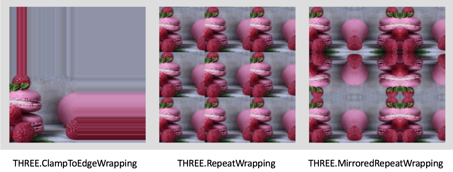
This picture from wrap-mode.html
illustrates the three wrapping methods that can be used (the default is
THREE.ClampToEdgeWrapping, which is rarely used):
Texture Tutor
Here is a basic tutor for texture mapping as we know it so far, based on a tutor by Nate Robins — experiment with the GUI controls to understand the basic concepts:
Lighting and Textures
So far, we've just mapped textures onto plain white surfaces. In fact, the texture is multiplied by the color of the surface. Consider the following demo:
Now, if the color of the face isn't direct color
(THREE.MeshBasicMaterial), but is a function of the
material (THREE.MeshPhongMaterial) and lighting of the
scene, you can easily see how we can combine this lighting information
with a texture.
One question, though, is what color the material should be. If the material has any hue, it might interact in odd-looking ways with the colors of the texture. Thus, it makes sense for the material to be gray. It should probably be a fairly light shade of gray, maybe even white, since lighting works by multiplying the material by a value less than one, so typically the result is darker than the original. However, it also depends on how many lights are in the scene, since the contributions of all the lights are added up, so colors can also get brighter, even over-driven. So, there's still some artistic judgment involved.
Consider the following demo:
The trick here is to create a Phong material and then to set
the .map property:
var mat = new THREE.MeshPhongMaterial();  // default is white
mat.map = texture;
Nearest and Linear Filters
When mapping texture onto a triangular face during the rendering process, Three.js:
- first determines which texture coordinates to use for each pixel touched by the triangular face
- then determines which texture color to use for each pixel, based on the texels (texture elements) around the computed texture coordinates
Pixels in the triangular face could be larger or smaller than the corresponding texels. In the picture below, the texture pattern on the left is very coarse and each texel is larger than the pixels in the image being rendered (shown in the center). For the texture pattern on the right, the texels are smaller than the pixels being rendered. (A couple pixel-sized elements are shown superimposed in green on the two texture patterns.)

The minFilter property of a THREE.Texture object controls how the
texture color is determined for the scenario on the left, and the magFilter property
specifies what to do for the scenario on the right. Two common options for both are
THREE.NearestFilter (select the color of the nearest texel) and
THREE.LinearFilter (linearly interpolate between the colors
of the four nearest texels). The two options can appear quite different,
as shown in the following demo:
choice of nearest texture color or linear interpolation between neighboring colors
Mapping onto a Box
We looked at this a little last time, but look at it again, and notice how we put a different material on each side of the box.
This demo maps three floral images onto the six sides of a cube:
Use your mouse to move the camera around to view all the sides of the cube. The
following code shows the TW.loadTextures()
function in action:
TW.loadTextures(["flower0.jpg", "flower1.jpg", "flower2.jpg"],
            function (textures) {
                displayBox(textures);
            } );
The first input is an array of file names for the multiple images.
Here is the code for the displayBox() function:
function displayBox (textures) {
    // box geometry with three floral images texture-mapped onto sides
    var boxGeom = new THREE.BoxGeometry(10,10,10);
    // palette of possible textures to use for sides
    var materials = [new THREE.MeshBasicMaterial({color: 0xffffff,
                                                  map: textures[0]}),
                     new THREE.MeshBasicMaterial({color: 0xffffff,
                                                  map: textures[1]}),
                     new THREE.MeshBasicMaterial({color: 0xffffff,
                                                  map: textures[2]})
                    ];
    // array of 6 materials for the 6 sides of the box
    var boxMaterials = [materials[0], materials[0], materials[1],
                        materials[1], materials[2], materials[2]];
    var boxMesh = new THREE.Mesh(boxGeom, boxMaterials);
    scene.add(boxMesh);
    TW.render();    // render the scene
}
In this case, a "palette" (array) of three materials is first
created, and then an array of six materials is constructed for
the six faces of the cube (it takes some trial-and-error to
determine the order in which the six faces are stored in the
box geometry, in order to achieve a desired arrangement of
the three image textures). Again, the scene is not rendered
until the images are all loaded and the displayBox()
function is invoked.
Mikey Cube
Here's a demo called Mikey Cube which has six pictures of Kelsey's dog Mikey.