Q: What is the parametric equation of a line from A=(3,1,8) to B=(6,5,2)?
Q: What is the parametric equation of a line from B=(6,5,2) to A=(3,1,8)?
The "centroid" of a polygon is the weighted sum of the vertices where all the weights are equal. It's one kind of "center" for a polygon. What is the centroid of a triangle with vertices:
A=(3,1,8)
B=(6,5,2)
C=(9,7,4)
If the vertices are colored Red, Green and Blue, respectively, what is the color of the centroid? What is the hue, saturation and value?
The vertex array was nice for a while, but it's too restrictive, particularly as we start using GLUT objects. From now on, we'll use twBoundingBox. It takes six arguments, which are the minimum and maximum x, y and z coordinates, in that order:
twBoundingBox(minx,maxx,miny,maxy,minz,maxz);
The arguments are (1) the minimum x value, (2) the maximum x value, and so forth.
The purpose of this call is to give TW the information it needs to set up the camera. If you want to see the bounding box for any of our TW demos, just right-click (command-click on the Macs) and choose "show bounding box" from the menu.
OpenGL is structured in three layers:
You can usually determine where something came from by its prefix: gl, glu, or glut, however, we will almost never care in this course. You can get a list of what each thing implements by looking at the header files:
/usr/include/GL/gl.h
/usr/include/GL/glu.h
/usr/include/GL/glut.h
These files are what gets included when you #include glut.h. (Each includes the previous in a daisy-chain way.)
Why do you suppose OpenGL was layered this way?
In the 02-ColorCube, we built a wire cube. It turns out that's already available in GLUT. Here are the built-in GLUT objects.
void glutWireSphere(GLdouble radius, GLint slices, GLint stacks);
void glutSolidSphere(GLdouble radius, GLint slices, GLint stacks);
void glutWireCone(GLdouble base, GLdouble height, GLint slices, GLint stacks);
void glutSolidCone(GLdouble base, GLdouble height, GLint slices, GLint stacks);
void glutWireCube(GLdouble size);
void glutSolidCube(GLdouble size);
void glutWireTorus(GLdouble innerRadius, GLdouble outerRadius, GLint sides, GLint rings);
void glutSolidTorus(GLdouble innerRadius, GLdouble outerRadius, GLint sides, GLint rings);
void glutWireDodecahedron(void);
void glutSolidDodecahedron(void);
void glutWireTeapot(GLdouble size);
void glutSolidTeapot(GLdouble size);
void glutWireOctahedron(void);
void glutSolidOctahedron(void);
void glutWireTetrahedron(void);
void glutSolidTetrahedron(void);
void glutWireIcosahedron(void);
void glutSolidIcosahedron(void);
As always, consult the man pages for all the details.
Example of using a GLUT object:
void display(void) {
    twDisplayInit();
    twCamera();
    glutWireCube(2);
    glFlush();
    glutSwapBuffers();
}
The argument to glutWireCube() is pretty straightforward: it's the length of any side of the cube. In the example above, the cube is 2x2x2. Since the origin is in the center, all the vertices have coordinates taht are at +/- 1, just like our ColorCube example
Spheres and cones both have "slices" and "stacks" as arguments. They come about because these curved surfaces are in fact rendered with polygonal approximations. Consider a circle. If you cut the perimeter into N parts, and use an N-sided polygon instead of a circle, OpenGL would say you are using N slices. For example, with N=3, you're approximating a circle with an equilateral triangle. With N=4, you're approximating it with a square. "Stacks" is just the same idea, but in another dimension. You should consider 3 to be the smallest value of either "slices" or "stacks." As N gets larger, your approximation is better: 5 is quick and dirty, 12 is pretty good, and so on.
Polygonal approximations can be pretty good, particularly in the interior of a solid object if you use smooth shading. However, the polygonal approximation can be apparent at the edges of the object; more precisely, in the silhouette. This problem is known as the silhouette edge problem. If your object will be silhouetted, you'll have to use more slices and stacks. This makes rendering slower. (An example of the general speed versus quality tradeoff.)
Look at demos/modeling/SilhouetteEdge.cc . This is a rendering of a wire sphere with keyboard callbacks to adjust the number of slices and stacks. As always, the "?" key will tell you the different callbacks. (Here, try 1, 2, 3, and 4.) How many stacks and slices give a pretty decent sphere?
The TW API defines the following for your use:
/* Draws unit barn (1 x 1 x 1) with colors specified for the sides and
roof.  The left front bottom of the barn is anchored at (0,0,0); drawn in
+x,+y,-z direction.  */

void twDrawBarn(twTriple sideColor, twTriple roofColor);

/* Creates a disk of given radius with the specified number of slices.
   This is just a wrapper for gluDisk */
void twDisk(GLfloat radius, GLint slices);

/* Creates a cylinder with the given radii for the base and the top, and
   the given height.  The cylinder is drawn solid (as opposed to wire
   frame) and has normal vectors generated. The cylinder does not have
   ends; for that, use twSolidCylinder.  The cylinder has the base in the
   z=0 plane and extends along the positive z axis.  This function is a
   wrapper for gluCylinder, so see the man page of that for more info. */

void twCylinder(GLfloat base,GLfloat top,GLfloat height,
		GLint slices, GLint stacks);

/* Like twCylinder, but draws the cylinder with closed ends; drawn from
center in x and z; oriented so that it is drawn downward from y = 0 */

void twSolidCylinder(GLfloat base,GLfloat top,GLfloat height,
		     GLint slices,GLint stacks);
Is there any disadvantage to using these? Why do you think we didn't use glutSolidCube for the color cube? What disadvantages are there to using twDrawBarn?
The main trouble is flexibility: with the color cube, I needed to make each vertex a different color. I just can't do that with the built-in objects: all the vertices go down the pipeline in one burst. That's convenient, but inflexible. So, if you use glutSolidCube(), it has to be all one color.
In order to use these built-in objects, we need a "handle" on it: a way to pick it up and put it where we want. But, where is the object? After all, an object occupies a collection of points, but for simplicity, we want to have a single point as the location of the object. For this course, we will call that the reference point of the object or the object's origin. That is, the "location" of an object is the origin of the coordinate system it's built in. For example, the handle for the barn is its lower left front corner, since that vertex is the origin. For the color cube, the handle is the center of the cube, since all its vertices have coordinates of +/- 1. In the case of the color cube, none of its vertices is its reference point; the center is.
We'll also need to know an object's orientation or local coordinate system. Alas, the man pages for the GLUT are sometimes pretty bad at that. Nevertheless, we'll manage.
Let's look again at our example of how to use a GLUT object:
void display(void) {
    twDisplayInit();
    twCamera();
    glutWireCube(2);
    glFlush();
    glutSwapBuffers();
}
DESCRIPTION: glutSolidCone and glutWireCone render a solid or wireframe cone respec- tively oriented along the Z axis. The base of the cone is placed at Z = 0, and the top at Z = height. The cone is subdivided around the Z axis into slices, and along the Z axis into stacks.This is pretty intelligible, though it requires some visualizing. The reference point is the center of the base of the cone, and the bounding box is defined by the radisu of the circular base and the height of the cone.
So, we've established that these calls to GLUT functions will draw particular objects for us; for example, glutSolidCube(1) produces a "generic" cube. How do we place instances of these objects in the scene?
The main technique is to use the following transformations to modify the coordinate system. We're changing from the "scene coordinate system" (AKA "scene frame") to the "object coordinate system" ("object frame").
These function calls transform the coordinate system. We call each such step a transformation. We can do as many as we want, so we can translate, rotate, translate again, rotate, scale and so forth.
Example: If you do the following:
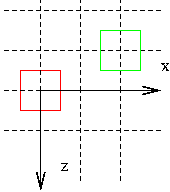
glColor3f(1,0,0);  // red
glutWireCube(1);   // cube A
glTranslatef(2,0,-1);
glColor3f(0,1,0);  // green
glutWireCube(1);   // cube B
Cube A, the red cube, is drawn around the origin. When OpenGL does the "glTranslatef()," the origin is moved to a point that is at location (2,0,-1) in the original coordinate system. Cube B, the green cube, is drawn around the new location of the origin. (After all, it sends exactly the same vertices down the pipeline.) But, because the origin has been relocated, the result looks different. The result might look like:
Rotation works similarly, except that you give the angle you want to rotate and the axis to rotate around. Typically, you rotate around one of the major axes (X, Y, or Z), but you can also rotate round bizarre axes like (2,3,1) if you want. (This is how the mouse-rotation is done in TW.)
Example: If you do the following:
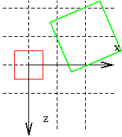
glColor3fv(1,0,0);  // red
glutWireCube(1);   // cube A
glTranslatef(2,0,-1);
glRotatef(30,0,1,0);  // rotate 30 degrees around Y axis
glColor3fv(0,1,0);  // green
glutWireCube(1);   // cube B
The green cube is drawn in a coordinate system that is rotated by 30 degrees around the Y axis. The result might look like:
Finally, we can scale the coordinate system. Typically, this is just a positive multiple, but you can also do other weird things. Here's a simple shrinking by two:
Example: If you do the following:
glColor3fv(1,0,0);  // red
glutWireCube(1);   // cube A
glTranslatef(2,0,-1);
glRotatef(30,0,1,0);  // rotate 30 degrees around Y axis
glScalef(2,2,2);     // double each axis
glColor3fv(0,1,0);  // green
glutWireCube(1);   // cube B
The green cube is drawn in a coordinate system that is rotated by 30 degrees around the Y axis and then expanded by a factor of 2. The result might look like:
Now, look at the code for this jumble of blocks: demos/modeling/Blocks.cc
It's important to remember that the initial coordinate system has the z axis coming out of the screen.
When you translate, rotate, or scale, you change the coordinate system for all subsequent operations; that is, you change the interpretation or meaning of vertices. The vertex (2,3,4) means something different as a result.
However, these are affine transformations, which means that lines stay lines and planes stay planes. Therefore, to transform a line, you transform the endpoints and draw the line between the transformed endpoints.
When we do all these transformations, we often want to return to our original coordinate system, to go on and place other objects. To do that, the easiest thing it so save the current transformation matrix (CTM) before doing the transformations, and then restore it afterwards. We can save a copy of the CTM on a stack, so the calls to do this have "push" and "pop" in their names:
For example, to place that green, rotated, expanded cube and then return to the coordinate system of the red cube, we do the following:
glColor3fv(1,0,0);  // red
glutWireCube(1);   // cube A
glPushMatrix();
glTranslatef(2,0,-1);
glRotatef(30,0,1,0);  // rotate 30 degrees around Y axis
glScalef(2,2,2);     // double each axis
glColor3fv(0,1,0);  // green
glutWireCube(1);   // cube B
glPopMatrix();
So, one take-home message of this reading is:
Define your object in a coordinate system that is convenient, then use affine transformations to place it in the scene.
In simple cases, we can usually place the GLUT object we want with a translate, a rotate and a scale, in that order.