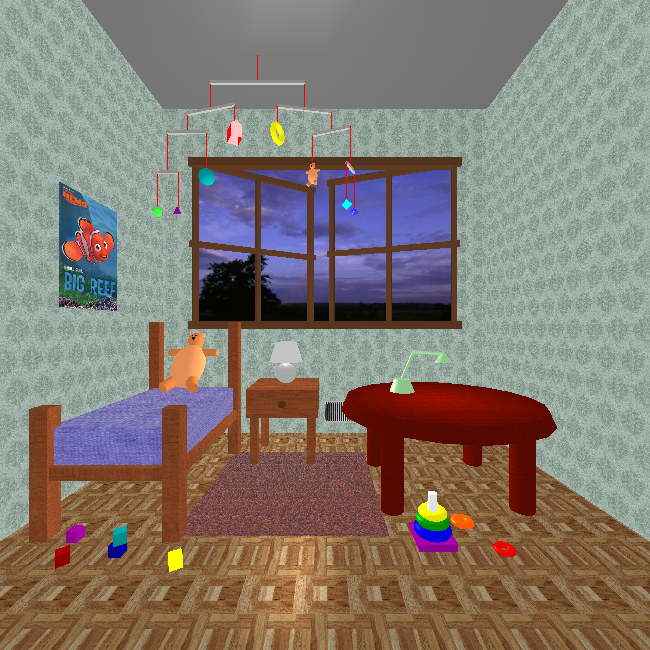

Texture mapping was one of the major innovations in CG in the 1990s. It allows us to add a lot of surface detail without adding a lot of geometric primitives (lines, vertices, faces). Think of how interesting Caroline's ``loadedDemo'' is with all the texture-mapping.
As with everything in computer graphics, most of what I know about texture mapping I learned from an early edition of Angel's book, so check that first. Unfortunately, the edition I read had one of his weakest chapters, because it didn't do a very good job of connecting the theory with the OpenGL code. A more practical presentation is a chapter of the Red Book (the Red OpenGL Programming Guide). You're encouraged to look at both.
In this reading, we'll start with some conceptual overview, then quickly look at practical examples, then we'll tour through the many settings, parameters and situations there are to consider.
Texture mapping paints a picture onto a polygon. Although the name is texture-mapping, the general approach simply takes an array of pixels and paints them onto the surface. An array of pixels is just a picture, which might be a texture like cloth or brick or grass, or it could be a picture of Homer Simpson. It might be something your program computes and uses. More likely, it will be something that you load from a orginary image file.
Demos: These all are part of the 307 demos list. You need not worry about the code yet. We'll look at it a bit later.
These are textures that are simple arrays that we have computed in JavaScript. They're mapped onto a plane.
These are textures that are loaded from separate image files.
Conceptually, to use textures, you must do the following:
(s,t) for each
vertex of your geometry
The graphics system ``paints'' the texture onto the polygon.
Texture mapping is a raster operation, unlike any of the other things we've looked at. Nevertheless, we apply textures to 2D surfaces in our 3D model, and the graphics system has to figure out how to modify the pixels during rasterizing (AKA scan conversion).
Since texture-mapping happens as part of the rasterizing process, let's start there.
When the graphics card renders a polygon, it (conceptually)
Note: standard terminology is that the polygon is called a fragment (since it might be a fragment of a Bézier surface or some such polygonal approximation to something). Thus, the graphics card applies a texture to a fragment.
This all happens in either in the framebuffer (the video memory that holds the pixels that are displayed on your screen) or an array just like it.
To do texture mapping, the graphics card must
We can have 1D or 2D textures, though almost always 2D. The texture parameters will be in the range [0,1] in each dimension. Note that if your texture array isn't square and your polygon isn't square, you may have to deal with changes in aspect ratio.
Your texture is always an array and therefore is always a rectangle. Mapping a texture to rectangles (as OpenGL objects) is fairly easy; mapping it to other shapes is likely to cause distortion. We'll need to be careful in those cases.
Associate each vertex of our polygon with a texture parameter, just
like we associate it with a normal, a color, and so forth. Three.js has
properties of a Geometry object devoted to representing the texture
coordinates for each vertex of a triangular face.
How do the texture coordinates relate to the 2D array of texels? This
is easiest to explain with a picture such as this one:
![]()
This is an array of 260 pixels, numbered from 0 to 259, arranged in a rectangular array that is 13 by 20 pixels. (Note, this is illegal in OpenGL and Three.js, because neither dimension is a power of two, but let's use it anyhow. )
[0][0] is the same as texture
coordinates (0,0).
[0][RowLength] ([0][19], which is element
19), we get to texture coordinates (1,0). This may seem
odd, but it's true.
[ColLength][0] ([12][0], which is element
240), we get to texture coordinates (0,1). Again, this may
seem odd, but it's true.
[ColLength][RowLength] ([12][19] which is
element 259) corresponds to texture coordinates
(1,1).
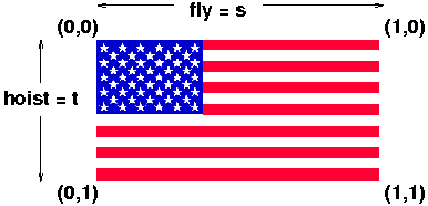
Conventionally, the texture coordinates are called (s,t),
just as spatial coordinates are called (x,y,z). Thus, we can
say that s goes along the rows of the texture (along
the ``fly'' of the flag). The t coordinate goes along
the columns of the texture (along the ``hoist'' of the flag).
Although you will often use the entire texture, so that all your texture coordinates are 0 or 1, that is not necessary. In fact, because the dimensions of texture arrays are required to be powers of two, the actual image that you want is often only a portion of the whole array.
The computed US flag array has that property. The array is 256 pixels wide by 128 pixels high, but the flag itself is 198 pixels wide by 104 pixels high. Thus, the maximum texture coordinates (if you just want the flag and none of the gray area) are:
fly = 198/256 = 0.7734 hoist = 104/128 = 0.8125
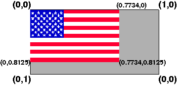
The result might look like the image above.
Of course, we also need to ensure that the rectangle we are putting the flag on has the same aspect ratio as the US flag, namely: 1.9. See the official US flag specification.
The texture parameters can also be greater than 1, in which
case, can use parameter settings to get repetitions of the
texture. If s is some parameter where 0 < s <
1, specifying some part of the texture partway along,
then 1+s, 2+s and so on are the same location in
the texture. Move this par
Here is a basic tutor for texture mapping as we know it so far, based on a tutor by Nate Robins:
Let's start with texture-mapping with computed textures. Because they're computed, they'll be very simple, but we use them for two reasons:
It's now time to look at the code for our first basic demo.
Here's the plane flags demo again. It's not important what's inside the code for creating checkerboards and such, but just realize that each returns an array of pixels. The most important lines of code are at the end.
Here's the essential part of the code. Look particularly at the
implementation of makeFlag(). I've tried to keep it as
simple as possible. The code below is just the code for
Notice that the texture is a property of the material, not the geometry. The geometry, however, defines (default) texture parameters for each vertex. (Texture parameters of individual pixels of a face are done by interpolation from the texture parameters of the face's three vertices.)
Everything else is similar to what we've seen before. View the source of the demo to get the complete program.
In the last section, we saw that geometry objects define texture coordinates for each vertex. Even earlier, we saw that we don't always want to use the default (0,1) texture coordinates. We might want to use (0.77,0.81) as the maximum texture coordinates with the US Flag. So, how can you change the default texture coordinates (or set them on your own geometry objects)?
In THREE.js, they put the texture coordinates in a property of
the THREE.Geometry called faceVertexUvs
(instead of using S and T, some people use U and V; both appear in the
THREE.js code). This property is an array of one element (so far as I
have yet determined), and that element is an array of face uvs
,
where a face UV is a three-element array, corresponding to the three
vertices of the face, and each element of that is
a THREE.Vector2 that captures the U and V values.
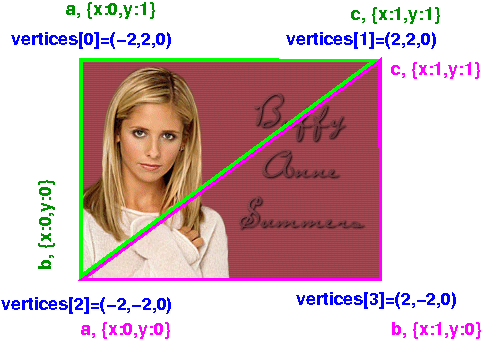
Let's try to understand that using a specific example. We'll consider the geometry object that we used to map Buffy's face on, earlier. It's a simple 2D plane (a rectangle):
planeGeom = new THREE.PlaneGeometry( 4, 4);
Let's look inside that data structure. First, the vertices:
JSON.stringify(planeGeom.vertices)
[{"x":-2,"y":2,"z":0},   // 0
 {"x":2,"y":2,"z":0},    // 1
 {"x":-2,"y":-2,"z":0},  // 2
 {"x":2,"y":-2,"z":0}    // 3
]
Nothing too surprising there. There are four vertices, with
all z=0, and the x and y values in +2 and -2. Now let's
look at the two faces, with their vertices defined as indexes into the
array above.
planeGeom.faces[0]
THREE.Face3 {a: 0, b: 2, c: 1, normal: THREE.Vector3, vertexNormals: Array[3]…}
planeGeom.faces[1]
THREE.Face3 {a: 2, b: 3, c: 1, normal: THREE.Vector3, vertexNormals: Array[3]…}
So, the two triangular faces are the upper left triangle and the lower right triangle. Finally, let's look at the UV values for each of the 6 vertices (three for each of the two faces):
> JSON.stringify(planeGeom.faceVertexUvs)
[
  // array of two elements
  [
   [{"x":0,"y":1},{"x":0,"y":0},{"x":1,"y":1}],  // elt 0 is for face 0
   [{"x":0,"y":0},{"x":1,"y":0},{"x":1,"y":1}]   // elt 1 is for face 1
  ]
]
Weirdly, the two coordinates are named "x" and "y" in these objects, rather than "u" and "v" as you might expect (or even "s" and "t").
Here's a picture that might help:
Consider the following function, which updates the S and T values for a
THREE.PlaneGeometry like we have:
Using that function, we can map our US flag onto the plane with no gray areas:
However, the code for doing that is unintuitive, because the default
THREE.js behavior is to flip the vertical texture parameter.
This is called .flipY. So, instead of wanting the T
parameter to go
We actually set it to go
That is, with a flipped Y, the upper left corner has coordinates of (0,1) and the lower left has coordinates of (0,0.2). To pull out just that piece, here's how we have to set the texture parameters:
updateTextureParams(flagGeom,0,0.75,1-0.81,1);
Here's the complete demo.
Here's a demo showing a image file being loaded and texture-mapped onto the same plane we've used before:
The code has one very tricky part, though. When we computed an array and used it as a texture, the array was already available for rendering. With an external image, there's going to be some delay before the data arrives from some network source. This delay might run to a few hundred milliseconds, but even a few milliseconds is an enormous amount of time compared to the speed that code is running in JavaScript.
Consequently, if the only rendering we did was right after the image was referenced, the code would not work at all. Here's pseudo-code for the situation I'm describing:
    var buffyTexture = new THREE.ImageUtils.loadTexture( "../../images/buffy.gif",
                                                         new THREE.UVMapping());
    var buffyMat = new THREE.MeshBasicMaterial(
        {color: THREE.ColorKeywords.white,
         map: buffyTexture});

    var buffyMesh = new THREE.Mesh( planeGeom, buffyMat );
    scene.add(buffyMesh);
    TW.render();
There simply isn't time for the image to load between that first line, when a request for the image is sent to the server, and the last line, when the scene is rendered. If you try this, the plane will be blank white.
The solution is to use an event handler. Event handlers are general-purpose solutions to code that you want to run after some event has happened. In this case, the event is that the image data has finally arrived from the server. The event handler can then invoke the renderer.
The way that THREE.js does this is also very standard: a function is passed in, and it will be invoked when the event occurs. Here's the improved code:
    var planeGeom = new THREE.PlaneGeometry( 4, 4);
    var imageLoaded = false;
    var buffyTexture = new THREE.ImageUtils.loadTexture( "../../images/buffy.gif",
                                                         new THREE.UVMapping(),
                                                         // onload event handler
                                                         function () {
                                                             console.log("image is loaded.");
                                                             imageLoaded = true;
                                                             TW.render();
                                                         });
    var buffyMat = new THREE.MeshBasicMaterial(
        {color: THREE.ColorKeywords.white,
         map: buffyTexture});

    var buffyMesh = new THREE.Mesh( planeGeom, buffyMat );
    return buffyMesh;
}
In the code above, we pass in an anonymous function to be the event handler. It gets invoked when the image finishes loading, and it renders the scene.
That's it! Later, we will get into more complex situations where you want to use umpteen images as textures: how do you figure out that they've all, finally, loaded, and the scene can be rendered?
In the rest of the texture-mapping reading, we'll discuss:
Here's what we learned
© Scott D. Anderson
This work is licensed under a Creative Commons License
Date Modified:

