Reading: Bézier Surfaces and Other 3D Shapes
This reading builds on the prior reading about Bézier curves, but now we look at surfaces: 2D "sheets". These are essentially quadrilaterals with wiggles, the same way that our curves were line segments with wiggles.
We'll then transition to using a 1D curve, including Bézier curves, as the silhouette of lathe geometry.
Then, we'll look at using a 1D curve, including Bézier curves, as the path for a tube geometry.
Finally, we'll take a quick look at extrusion geometries.
Representing Surface Patches
Using a parametric representation, each coordinate (of an XYZ point in 3-space) becomes a function of two new parameters, which we will call $s$ and $t$, just like we did with textures (which is why $u$ and $v$ are sometimes used instead).
If we had coefficients, $C_{ij}$, we could define the surface like this:
$$ \begin{array}{rcllll} P(s,t) &=& C_{00} + &C_{01}t + &C_{02}t^2 + &C_{03}t^3 + \\ & & C_{10}s + &C_{11}st + &C_{12}st^2 + &C_{13}st^3 + \\ & & C_{20}s^2 + &C_{21}s^2t + &C_{12}s^2t^2 + &C_{23}s^2t^3 + \\ & & C_{30}s^3 + &C_{31}s^3t + &C_{22}s^2t^2 + &C_{33}s^3t^3\\ \end{array} $$
or
$$ P(s,t) = \sum_{i=0}^{3}\sum_{j=0}^{3} C_{ij}s^it^j $$
Since there are 16 coefficients, we need 16 control points to specify the surface patch.
Alternatively, we can define the surface using the blending functions, based on the Bernstein Polynomials that we saw last time. Some useful references:
\[ b_{i,d}(t) = \Choose{d}{i} t^i(1-t)^{d-i} \]
The $d$ above is the degree of the curve. We'll use cubics, so $d=3$:
\[ b_{i}(t) = \Choose{3}{i} t^i(1-t)^{3-i} \]
So, a 1D Cubic Bézier curve would be:
\[ P(t) = \sum_{i=0}^3 C_i\cdot b_{i}(t) \]
where $C_i$ is the $i$th control point.
The 2D version is more complicated, but similar:
\[ P(s,t) = \sum_{i=0}^3 \sum_{j=0}^3 C_{ij}\cdot b_{i}(t)b_{j}(s) \]
Intuition
Note that the four edges of a Bézier surface are Bézier curves , which helps a great deal in understanding how to control them. That helps us to understand 12 of the 16 control points.
The four interior points are harder to interpret. Concentrating on one corner: if it lies in the plane determined by the three boundary points, the patch is locally flat. Otherwise, it tends to twist. This is hard to picture.
The twist is related to the double partial derivative of the curve, if that's helpful (but for most students it's not):
$$ \frac{\partial^2 p}{\partial u\partial v}(0,0) = 9(p_{00} - p_{01} + p_{10} - p_{11}) $$
However, if we think of the blending functions, these interior points are still pulling the patch towards them, so we can often get what we want with a little experimentation.
The following online visualiztion of Bézier surfaces is an excellent way to get some intuition. Take a few minutes to play around with it.
Dome Demo
The following demo of a "dome" is very symmetrical, but demonstrates a Bézier surface in Threejs:
Bézier Patch in Three.js
Before we dig into the code, let's visualize the control points:

Notice that the (0,0) corner of the surface is at the lower right. (Just like texture coordinates.)
However, I find it awkward to start in the lower right, so I like to
write the control points down "top to bottom" and then simply reverse
that list before creating the geometry. Rather like the flipY
setting for texture-mapping.
Therefore, I defined the control points of the dome like this:
const topToBottom = [
    [ [0,3,0],  [2,4,1],  [4,4,1],  [6, 3, 0] ],
    [ [-1,2,0], [2,2,1],  [4,2,1],  [7, 2, 0] ],
    [ [-1,1,0], [2,1,1],  [4,1,1],  [7, 1, 0] ],
    [ [0,0,0],  [2,-1,0], [4,-1,0], [6, 0, 0] ],
];
Computing The Surface
Unlike Bézier curves, Threejs has decided to discard direct support
for Bézier surfaces. Instead, we're expected to use an general
class for 2D parametric surfaces, available not in the core
Threejs, but in the addons.
To load that class, we have to put the following in the top of our main.js file:
import { ParametricGeometry } from 'three/addons/geometries/ParametricGeometry.js';
The example on the Threejs website has the following code:
const geometry = new THREE.ParametricGeometry( klein, 25, 25 );
const material = new THREE.MeshBasicMaterial( { color: 0x00ff00 } );
const klein = new THREE.Mesh( geometry, material );
scene.add( klein );
Even their example is flawed, since the klein variable is used
twice, once as the first argument to ParametricGeometry and again as
the variable holding the resulting mesh. So, JavaScript would complain
about the second assignment. Or maybe the Threejs folks are making a
very obscure and erudite joke about Klein
Bottles.
That argument needs to be a function of three arguments, s, t, and
P. The (s,t) are the parameters of the location on the surface, the P
is a Vector3 that the function should fill with the point on the
surface. In other words, it's up to us to compute the
point. Fortunately, we know how to do that, as we saw at the top of
this reading, but which we'll repeat here:
\[ P(s,t) = \sum_{i=0}^3 \sum_{j=0}^3 C_{ij}\cdot b_{i}(t)b_{j}(s) \]
Computing the Blending Functions
So, we have to define the blending functions ourselves. Okay, deep breath, we can build this up. Let's first remind ourselves of the binomial coefficient:
$$ \Choose{n}{i} = \frac{n!}{(n-i)!i!} $$
Let's take an example:
$$ \Choose{10}{6} = \frac{10!}{6!4!} $$
If we cancel the 6!, we get:
$$ \frac{10\cdot 9\cdot 8\cdot 7}{4\cdot 3\cdot 2\cdot 1} $$
which we can rewrite as:
$$ \frac{10}{1}\cdot \frac{9}{2} \cdot\frac 83 \cdot \frac74 $$
In general:
$$ \Choose{n}{k} = \prod_{i=1}^k \frac{n+1-i}{i} $$
Here's a simple JS function to compute exactly that:
function binomial(n, k) {
  let res = 1;
  for (let i = 1; i <= k; i++) {
    res = res * (n + 1 - i) / i;
  }
  return res;
}
The bernstein coefficient is just:
\[ B_{i,n}(t) = \Choose{n}{i} t^i (1-t)^{n-i} \]
Here's a JS function to compute that:
function bernstein(n, i, t) {
  return binomial(n, i) * Math.pow(t, i) * Math.pow(1 - t, n - i);
}
Now, we can a point on the curve like this:
\[ P(s,t) = \sum_{i=1}^3 \sum_{j=1}^3 C_{ij} B_{i,3}(s) B_{j,3}(t) \]
Here's a JS function to compute that, except that instead of returning
$P(s,t)$ it stores the point in the target argument:
function bicubicBézier(s, t, target) {
  target.set(0, 0, 0);
  for (let i = 0; i <= 3; i++) {
    for (let j = 0; j <= 3; j++) {
      const b_i = bernstein(3, i, s);
      const b_j = bernstein(3, j, t);
      // because s and i go across the rows, left to right,
      // i needs to be the *second* argument to the
      // controlPoints
      const cp = controlPoints[j][i];
      target.x += cp.x * (b_i * b_j);
      target.y += cp.y * (b_i * b_j);
      target.z += cp.z * (b_i * b_j);
    }
  }
}
Note that this function references a global variable controlPoints
that contains a 2D array of control points. (Later, we'll see how to
improve that.) Meanwhile, the bicubicBézier function is exactly
what we need as an argument to the ParametricGeometry function. So,
we can make the dome like this:
function makeDome(slices=8, stacks=8, showMesh=false) {
    const geometry = new ParametricGeometry(bicubicBézier, slices, stacks);
    const material = new THREE.MeshNormalMaterial({ side: THREE.DoubleSide });
    const mesh = new THREE.Mesh(geometry, material);
    scene.add(mesh);
    return mesh;
}
makeDome(8,8,true);
And there's our demo to create a cubic Bézier surface:
General-Purpose Helper Functions
The function bicubicBézier is really useful for creating the
surface, but it "hard-wires" the global variable that contains the
control points, which makes it specific to this surface instead of
being a general-purpose helper function. Let's see if we can do
better.
What we need is to be able to dynamically create a function like
bicubicBézier, where the dynamically created function is able to
refer to a supplied array of control points. Fortunately, JavaScript
has a powerful mechanism called
closures,
and we can use them to good effect here.
The following function does the trick:
/* Function that returns a function suitable as an argument to
   THREE.ParametricGeometry. That function uses the argument
   controlPoints to compute a point on the 2D cubic Bézier, given
   parameters s and t. The 'target' argument is a Vector3 object which
   is used to store the result. The returned function has no return
   value. */

function bicubicBézierFunction(controlPoints) {
    return function bicubicBézier(s,t,target) {
        target.set(0, 0, 0);
        for (let i = 0; i <= 3; i++) {
            for (let j = 0; j <= 3; j++) {
                const b_i = bernstein(3, i, s);
                const b_j = bernstein(3, j, t);
                // because s and i go across the rows, left to right,
                // i needs to be the *second* argument to the
                // controlPoints
                const cp = controlPoints[j][i];
                target.x += cp.x * (b_i * b_j);
                target.y += cp.y * (b_i * b_j);
                target.z += cp.z * (b_i * b_j);
            }
        }
    }
}
Most of that code is the bicubicBézier function, which we've seen
before, so ignore that. Let's focus on the structure of the overall
function:
function bicubicBézierFunction(controlPoints) {
    return function bicubicBézier(s,t,target) {
        ...
    }
}
You see that that the return value is a function. We said at the beginning of the course that in JavaScript, functions are first class, which means they can be treated like data, including passing them as argument to other functions. Here, we are returning a function.
It happens that I named that returned function (bicubicBézier), but
I could just as well have left it anonymous; it works exactly the same
either way. In short:
bicubicBézierFunctionreturns a dynamically created function calledbicubicBézier
So, how do we use this? Here's how we can build our dome:
function makeDome(slices=8, stacks=8, showMesh=false) {
    const paramFunction = TW.bicubicBézierFunction(domeControlPoints)
    const geometry = new ParametricGeometry(paramFunction, slices, stacks);
    const material = new THREE.MeshNormalMaterial({ side: THREE.DoubleSide });
    const mesh = new THREE.Mesh(geometry, material);
    scene.add(mesh);
}
makeDome(8,8,true);
Notice the first line of makeDome, which is a call to
TW.bicubicBézierFunction passing in the desired control points. The
return value is a function that we turn around and pass to
ParametricGeometry. We never need the name of the function, so it
could have been anonymous. All the rest of the code is exactly the
same. Here's a demo using this new coding technique:
I've put the helper functions binomial and bernstein into TW, as
well as bicubicBézierFunction.
Flag
We can make a different surface, looking a little like a flag flapping in the wind, and texture-map a flag texture onto it. We can even use material and lighting. The surface normals are computed from the Bézier surface.
The Utah Teapot
One of the important milestones in the history of computer graphics was the Utah Teapot, created by CG pioneer Martin Newell
It was created in 1975 as a demonstration of the power of cubic Bézier patches. (The story is that Allen Newell and his colleagues had developed the idea of using Bézier patches to model curved surfaces, and that they were looking for a good example. One day, Professor Newell was looking at his wife's teapot and decided that it would be perfect.) Each Bézier patch handles a small part of the teapot. Since a Bézier curve can do a good approximation of a quarter circle, each Bézier patch goes one-quarter of the way around the pot (or the spout or the handle). So it takes 4 of them to go around the teapot. In the full teapot, there are 32 4x4 cubic Bézier patches.
Threejs provides the teapot, more in recognition of its historic importance than because you will find important uses of teapots in your scenes.
It is, naturally, in the addons; so you load it like this:
import { TeapotGeometry } from 'three/addons/geometries/TeapotGeometry.js';
Here's a demo:
and here's a screenshot from that demo:
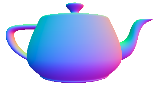
While the notion of modeling a teapot may seem silly, I think the result is pretty darn impressive. And this was done in 1975!
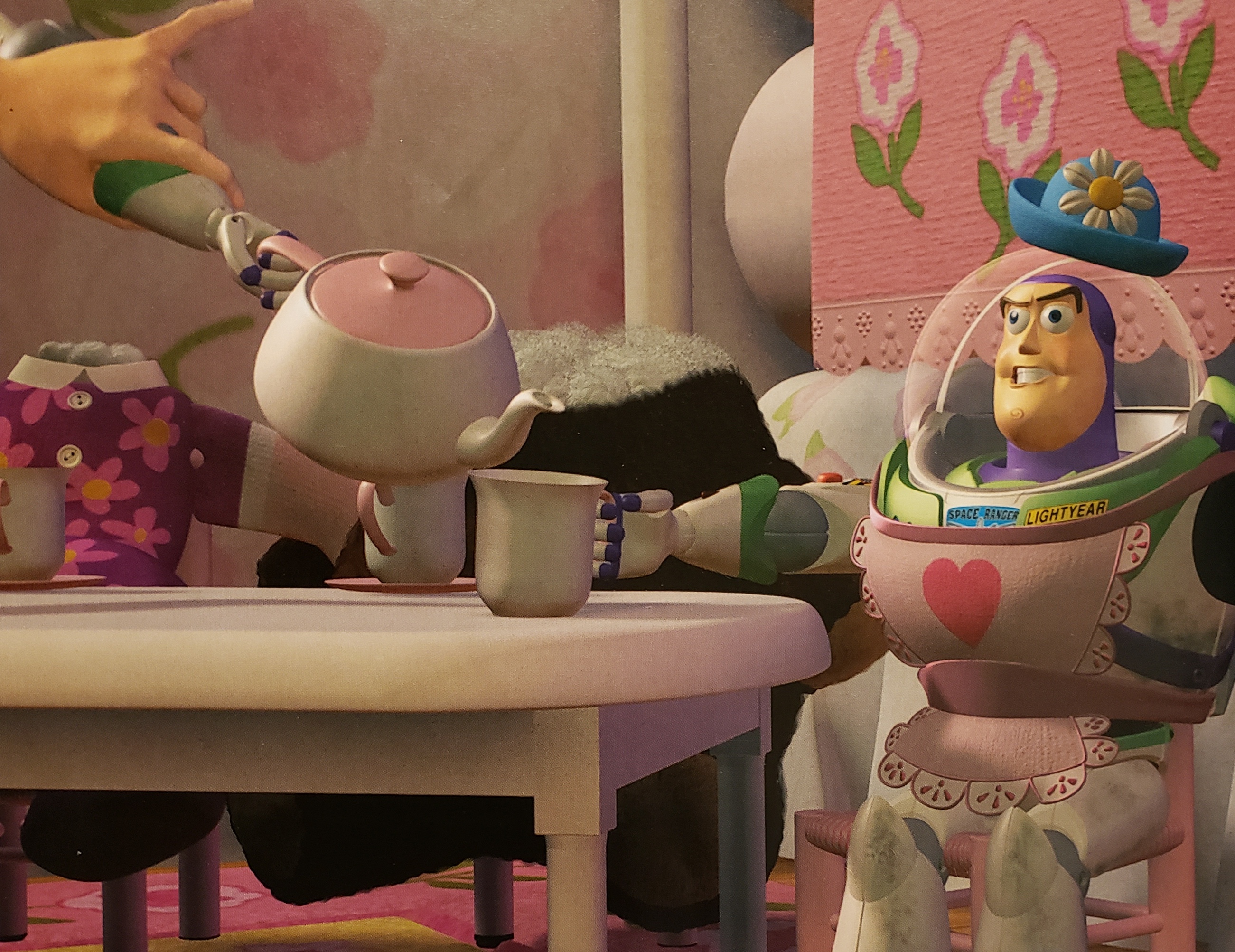
There is an homage to the Utah Teapot in the Toy Story, which was another important milestone in the history of CG. That movie, made in 1995, was the first feature-length film made entirely with computer graphics. Here's part of a frame from the movie:
Lathe Geometries
Now that we've seen some bicubic Bézier surfaces, let's turn to other kinds of curved surfaces. An important and useful one is a LatheGeometry
In wood-working and metal-working, a lathe is a machine for making objects like table legs and such, where every cross-section is a circle. (A potter's wheel is a similar idea.) Here's a picture:
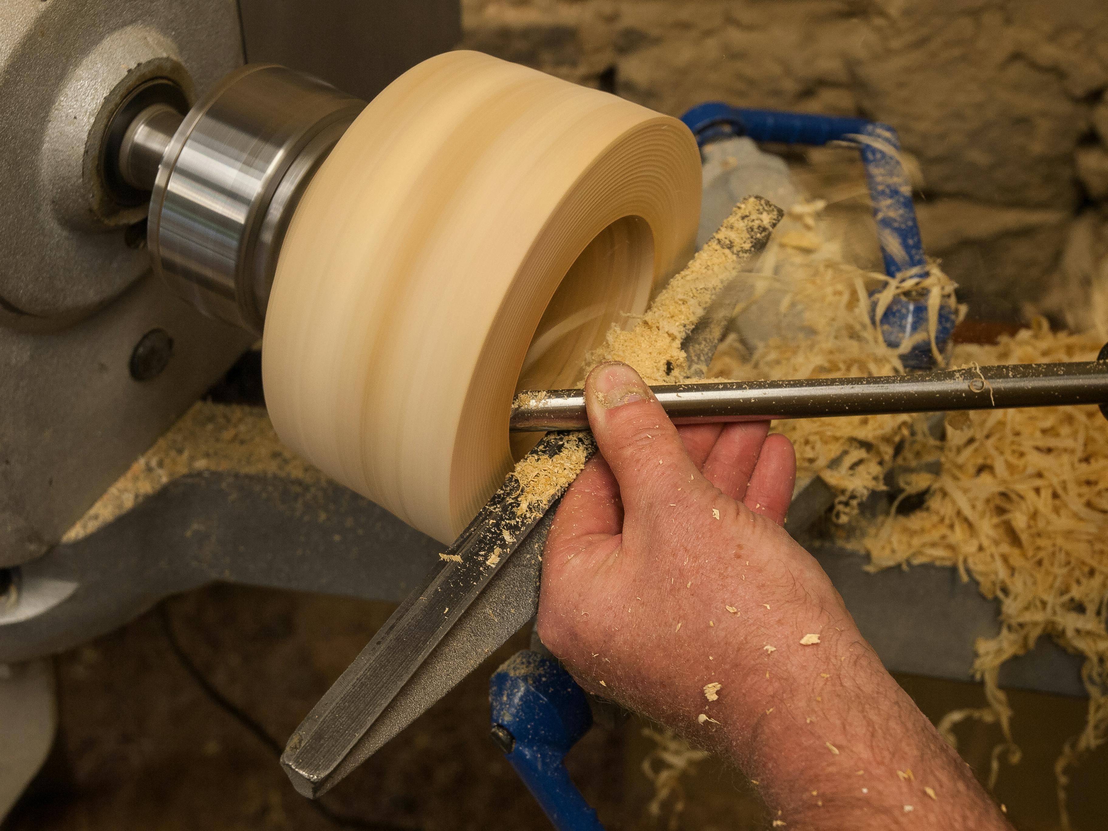
We can do the same thing in Threejs: all we need is information about the radius of the object at each point along its axis.
In Threejs, the axis of symmetry (the axis around which lathe "rotates") is the Y axis. So, each circular cross-section lies in a plane of constant Y.
Having chosen a Y value, we only need the radius of the circular cross section. We will represent that with an X value.
Lathe Funnel
Let's start with a very simple example. Suppose our data looks like this:
| X | Y |
|---|---|
| 1 | 0 |
| 2 | 10 |
| 15 | 22 |
What that means is that at Y=0, the radius is 1, when Y=10, the radius is 2, and when Y=22, the radius is 15. The resulting lathe object might look like this:
(I have a funnel in my kitchen at home that looks a lot like this.)
The code is remarkably simple:
const outline = [
    [1, 0],
    [2, 10],
    [15, 22 ]
];

function makeFunnel(outline) {
    // these are Vector2, not Vector3
    const pts = outline.map(a => new THREE.Vector2(...a));
    const geo = new THREE.LatheGeometry(pts);
    const mat = new THREE.MeshNormalMaterial({ side: THREE.DoubleSide });
    const mesh = new THREE.Mesh( geo, mat );
    scene.add(mesh);
    return mesh;
}
makeFunnel(outline);
Lathe Kiss
Armed with our knowledge of Bézier curves, we could compute the outline (silhouette) of the lathe object using Bézier curves.
Let's make an object that looks a bit like a Hershey's KissTM:
To do this, let's start by creating the silhouette, using control points of a Bézier curve. Note that this will be a 2D curve, since we only need XY values, not Z:
const kissControlPoints = [
    [0, 20],
    [8, 4],
    [12, 5],
    [12, 0],
];
Try to picture that. For example, the (0,20) means that the radius at the top of the kiss (Y=20) is zero. At the bottom of the kiss (Y=0), the radius is 12.
TODO: add picture of these control points
Now, we need to create a Bézier object, sample it to get a list of 2D points, and build our lathe geometry:
/* given the control points for a Bézier curve that is the silhouette
 * of a lathe geometry, create an return a lathe geometry with that
 * silhouette. The "stacks" variable is the number of circular
 * cross-sections (Y values) and the "slices" variable is the number
 * of segments on each circle (think of it as slices of pizza).
*/

function makeBézierLatheGeometry(cp, stacks, slices) {
    // note that these are Vector2, not Vector3
    const vecs = cp.map( a => new THREE.Vector2(...a) );
    // note that this is CubicBézierCurve not CubicBézierCurve3
    const curve = new THREE.CubicBézierCurve(...vecs);
    const pts = curve.getPoints(stacks);
    const geo = new THREE.LatheGeometry(pts, slices);
    return geo;
}
Finally, we make the mesh in the usual way:
function makeKiss() {
    const geo = makeBézierLatheGeometry(kissControlPoints, 20, 32);
    const mat = new THREE.MeshNormalMaterial({ side: THREE.DoubleSide });
    const mesh = new THREE.Mesh( geo, mat );
    scene.add(mesh);
    return mesh;
}
makeKiss();
Amazing!
Lathe Bottle
We could do the same thing with our coke bottle silhouette and create a 3D coke bottle using lathe geometry.
Tube Geometries
Another way to create a 3D object from a 1-dimensional curve is to use the curve as the central axis and move a circle along that axis, creating a tube. To do that, Threejs provides a TubeGeometry
In their example, which is pretty good, the central axis is a custom
sine curve, defined as a new class called CustomSinCurve as a
subclass of the Threejs Curve class. However, we haven't learned how
to define classes (as in Object-Oriented Programming), so that might
be difficult to understand.
Instead, let's use a class we have already used, namely
CubicBézierCurve3 which we used last time to define the s-curve, the
box-curve, and others. Let's create a tube out of the box-curve:
The code is surprisingly easy, given our earlier work with the
s-curve1 (where we explicitly create an instance of
CubicBézierCurve3) and the box-curve Bézier curve.
function makeTube() {
    scene.remove(tube);
    const vecs = controlPoints.map( a => new THREE.Vector3(...a) );
    const curve = new THREE.CubicBézierCurve3(...vecs);
    const geo = new THREE.TubeGeometry(curve,
                                       params.tubularSegments,
                                       params.radius,
                                       params.radialSegments,
                                       params.closed);
    const mat = new THREE.MeshNormalMaterial();
    tube = new THREE.Mesh( geo, mat );
    scene.add(tube);
}
makeTube();
In the code above, instead of sampling the Bézier curve to get a bunch
of points, we supply the object to THREE.TubeGeometry, because it
will sample the curve as it needs to.
The other arguments to TubeGeometry are straightforward:
- the number of segments along the tube
- the radius of the tube
- the number of segments around the tube (like the slices above)
- whether to join one end to the other.
If you'd like to do more with tube geometries and/or would like to learn how to define custom classes in JS, let me know.
Extrude
Another way to create a 3D object from a lower-dimensional shape is extrusion. Maybe when you were a child, you played with clay or Play-DohTM with a device like this:
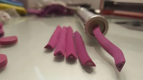
You put clay in at one end and force it through a 2D shape, yielding a long piece of clay with the 2D shape as its cross-section.
Threejs provides this feature via ExtrudeGeometry
In a way, extrusion is like a tube, except that the 2D shape is not a circle (and the axis is straight). Unfortunately, we have to learn a new language to define the 2D shape. This is done with the Shape class. We won't go deeply into this language, but we can if you would like. For now, let's look at one of the Threejs demos, namely the one for
It's a heart shape! Moreover, it's made from Bézier pieces, so with just a little work, we can easily understand this language. A few ideas to note, first. The API is Turtle Graphics, which means that you imagine a turtle dragging a pen around the 2D Cartesian plane, making lines as it moves. It can lift the pen to stop drawing and move to another location, and then it can put the pen back down.
Take a moment to go to the Wikipedia page on Turtle graphics, which has a nice animation:
In a moment, we'll try to understand the Threejs heart shape, but first, let's start with our heart shape. Here's the demo:
Here's the code:
// from our original heart shape, but not used
const controlPoints = [
    [0,2,0]
    [1,3,0],
    [1,1,0],
    [0,0,0],
];

const heartShape = new THREE.Shape();

heartShape.moveTo(0,2);
heartShape.bezierCurveTo( 1, 3, // heading towards here
                          1, 1, // finishing as if from here
                          0, 0 ); // finishing here
heartShape.bezierCurveTo( -1, 1,  // heading towards here
                          -1, 3,  // finishing as if from here
                          0, 2 ); // finishing here

const geometry = new THREE.ShapeGeometry( heartShape );
const material = new THREE.MeshBasicMaterial( { color: "red" } );
const mesh = new THREE.Mesh( geometry, material ) ;
scene.add( mesh );
We start by moving the turtle to (0,2), which is the dent at the top of the heart, and it's our first control point. Then, we draw a cubic Bézier curve to the origin, around the right side of the heart.
The bezierCurveTo method takes six arguments, and these are pairs
of (x,y) coordinates, so it's better to think of it as taking three
arguments that are points.
But don't we need four points to draw a cubic Bézier? Yes! The
method omits the first control point, because that is implicit: it's
the current location of the turtle. So, for the first Bézier, we
implicitly start at (0,2), because of the previous moveTo.
Then, without picking up the pen, we draw our second Bézier, ending back at the dent. Notice how the control points are in the reverse order, because we are now moving up the left side of the heart.
When that's all done, and we've created our shape, we hand that
Shape object to ShapeGeometry, and the rest is straightforward.
The Threejs heart code is written in an odd way, so I've made a few modifications, but the result works:
Here's the relevant code:
const heartShape = new THREE.Shape();

heartShape.moveTo( 5, 5 );
heartShape.bezierCurveTo( 5, 5,
                          4, 0,
                          0, 0 );
heartShape.bezierCurveTo( -6, 0,
                          -6, 7,
                          -6, 7 );
heartShape.bezierCurveTo( -6, 11,
                          -3, 15.4,
                          5, 19 );
heartShape.bezierCurveTo( 12, 15.4,
                          16, 11,
                          16, 7 );
heartShape.bezierCurveTo( 16, 7,
                          16, 0,
                          10, 0 );
heartShape.bezierCurveTo( 7, 0,
                          5, 5,
                          5, 5 );

const geometry = new THREE.ShapeGeometry( heartShape );
const material = new THREE.MeshBasicMaterial( { color: 0x00ff00 } );
const mesh = new THREE.Mesh( geometry, material ) ;
scene.add( mesh );
With a bit of graph paper and some patience, we can follow this shape.
Another inspiring example is this one by Jos Dirksen, author of an excellent book on Learning Threejs. To respect his copyright, this example will only be available on campus (or with htaccess credentials — ask Scott):
The Threejs site also has some very nice examples:
If you want to learn more about the methods for drawing 2D shapes, the important Threejs classes are
The Threejs shape API is very similar to the 2D WebGL canvas API, which has excellent documentation on the Mozilla Developer's Network. The Mozilla Developer's Network (MDN) are the people who create Firefox. It's a fantastic resource, highly recommended.
Here's a link to their Canvas Tutorial
Summary
In this reading, we've learned a number of ways of creating geometry objects in Threejs:
- 2D Bézier surfaces, which we used for the dome and the flag
- Lathe geometries, where the silhouette is series of points, including a 1D Bézier curve
- Tube geometries, where the axis of the tube is a
Curveobject, particularly aBézierCurve3object - Extrude geometries, where the axis is a straight line, but the object is a 2D shape, defined by Turtle graphics, including Bézier curves
To create 2D Bézier surfaces, we had to learn about
ParametricGeometry
which takes an argument that is a function of (s, t, v) where (s,t)
are the parameters of the location on the surface, and v is the
Vector3 to store the computed point in. We wrote code to compute the
Bernstein blending functions for Bézier curves and created a function
to create argument functions to ParametricGeometry.
The ParametricGeometry object is very general, so we could use it
define other kinds of surfaces.
For some of the techniques in this reading, we've just begun to dig into the complexities, but we have a good start for learning more. Talk to Scott if you want to go deeper.