Reading: Introduction to OpenGL/WebGL, Three.js, and the Barn
While we all want to get to the meat of the course as soon as possible, I've found that students sometimes get confused by jargon like "API" or "raster." So, this reading may sometimes cover things that you are personally familiar with. Please be patient.
Nevertheless, I'm going to keep a lot of this very high-level. We'll get into the details much later in the course. If you are interested before then (or anytime), please feel free to ask.
- Overview
- What is an API?
- Modeling
- Rendering
- The OpenGL Pipeline
- Geometry Data Structures
- Front and Back of Triangles
- Normal Vectors
- Points and Vectors in Three.js
- Drawing in Three.js
- Coordinates
- Creating a Simple Scene with Three.js and TW
- Prelude Code
- Building the Scene
- Building a Mesh
- Postlude Code
- Code Summary
- The Barn Code
- Three.js Fundamentals
- Learning More Three.js
- Summary
Overview
To get started with graphics programming, we need to introduce a number of important, but somewhat disparate topics. By the end of this reading, you should be able to understand all of the example code for the several simple demos.
The topics we'll cover are:
- what an API is, and the three APIs we'll use in CS307: OpenGL/WebGL, Three.js, and TW
- how information is stored and processed in OpenGL/WebGL
- some geometrical objects that we'll want to be able to draw, and how they're defined in OpenGL/WebGL and Three.js
- how to create a simple scene using Three.js and TW
After all this, we'll finally be ready to read the code for the barn..
What is an API?
An Application Programmer Interface is a set of programming elements (types, variables, functions, and methods) that enable some new capability or allow the programmer to interact with a piece of hardware, such as a robot or a graphics card.
We have three APIs in CS 307:
1. WebGL. This is a standard graphics API, a subset of the full OpenGL API that is supported by most graphics cards. (I'll use the terms "OpenGL" and "WebGL" interchangeably.) OpenGL/WebGL is about modeling and rendering. The specification is documented in the online man pages, but these are difficult to read at best. Fortunately, we will use very little of this directly, because we are using Three.js. Later in the course, we'll dig into these
2. Three.js This is an API built on top of WebGL, doing a lot of the modeling and rendering for you. WebGL is still there, underneath, but we will rarely see it. Three.js is very powerful. It allows you to ignore a lot of detailed technical concepts in Computer Graphics that plain WebGL would force you to know, and the programming is far less work. I think that using Three.js and learning the basic concepts is a good combination for this course. Your JavaScript code might look like this:
var boxGeom = new THREE.BoxGeometry(1,2,3); // width, height, depth
3. TW. This is Scott Anderson's home-grown API that packages up
certain common operations in our Three.js programs. It is layered on
top of Three.js — a thin layer at that! It does things like setting up
a camera for you and allowing you to toggle whether to show the
coordinate axes. All of these functions are available in the TW
object, so your JavaScript code might look like this:
var boxMesh = TW.createMesh( boxGeom );
...
TW.cameraSetup( args );
Don't worry if you don't yet understand this code. The point is the syntax.
The TW API is written in JavaScript, Three.js and WebGL. You are always welcome and encouraged to read the code (see below). It may change from time to time, since it's still under development, but that should be transparent to you.
You are welcome to read the TW source code if you'd like, but you're probably not ready for it yet. But it's not a secret, and I'm happy to explain it to you.
Modeling
In Computer Graphics, modeling means to represent some physical, 3D object as a data structure of points, vertices, faces, etc. For example, a 3D box has 8 corners (vertices), 12 edges, and 6 faces:
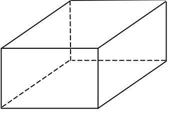
This representation is called the geometry of the object.
Objects also have material. A box might be made of some dull brown material or Tiffany blue.
We need both kinds of information to determine what an object looks like. The combination of those two kinds of information is called a mesh.
Figuring out what a mesh looks like is called rendering.
Rendering
When we render a scene, we don't just need the collection of meshes. We also need to know information like:
- where the camera is and how it is pointing
- what lights there are, where they are an how bright and what color they are
For example, the sides of our Tiffany blue box might all be the same material, but the sides facing the light will be, well, lighter.
The output of the rendering is a 2D picture that is shown on your computer monitor. This rendering is almost always a raster (a raster is a rectangular arrangement of pixels) image of pixels (a pixel is a single "picture element" — a single spot of color).
The OpenGL Pipeline
The OpenGL API and the graphics card are implemented as a pipeline. (Those of you who have taken a computer architecture course will be familiar with this term.) What does that mean? It means that your calls to the OpenGL functions (or to code that eventually calls the OpenGL functions) will often put data into one end of a pipeline, where they undergo transformations of various sorts, finally emerging at the other end. The other end of the OpenGL pipeline is the monitor, or some graphics output device.
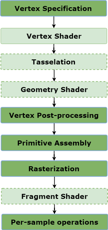
No need to worry about what those steps are yet. If you are curious now, you can read a lot more at Rendering Pipeline Overview. We will talk more about the details of this pipeline much later in the course.
Essentially, we put vertices of objects (and other information about materials, lights, and the camera) into one end of the pipeline and get image pixels out the other end.
Of course, that's not the only thing that happens. Some API functions modify the pipeline, such as specifying lighting, so that subsequent computations are modified in different ways. For efficiency, the pipeline hangs onto some information and other information just slips through, with only pixels to show for it. That is, some data is not retained. In particular, vertices are not retained. So, "the box" does not exist as far as the rendering pipeline is concerned. If we want to look at the barn from a different angle, we have to move the camera and render it again (by "render," I mean send all the vertices down the pipeline again, converting them to pixels).
In Three.js, we build data structures of vertices and faces, and when the scene is rendered from a particular viewpoint, the mathematics of the pipeline is re-executed with these values. The graphics card has memory, called buffers, that can be used to retain vertex values and attributes, avoiding the cost of re-sending the vertices down to the graphics card, which would otherwise be a performance bottleneck. Three.js does this for us.
Geometry Data Structures
The simplest things that OpenGL/WebGL can draw are objects that you're familiar with from the time you were first able to hold a crayon. However, some of them are a little different in OpenGL/WebGL and in Three.js. Also, how they're drawn is, perhaps, not what you'd think.
Points/Vertices. These are just dots. In math, points have location and nothing else (e.g. no area, so no color). We will use vertices to construct geometrical objects.
Vectors. These are arrows. In math, vectors have direction and magnitude and nothing else. You can't draw vectors in OpenGL, but they are used a lot. For example, vectors are used to specify the orientation of the camera, the direction of a light ray, and the orientation of a surface that the light is falling on. We won't see any vectors at first, but we'll be getting to them soon.
Line Segments. In graphics, we are almost never interested in lines, which are infinite. Instead, we're almost always interested in line segments, defined by their endpoints. A line segment is just a pair of points/vertices.
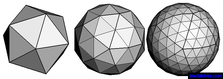
Triangles. For almost any real object, we don't want lines, we want surfaces, and the representation of a surface is often done by breaking it down into triangles, often an enormous number of triangles. One great and important advantage of triangles is that they are necessarily planar (flat) and convex (no dents), and bad things can happen if you try to draw a polygon that is either non-planar or concave. Those bad things can't happen if you draw triangles. Three.js uses triangles as its universal representation of geometry, even if the API call says that you're building, say, a sphere or a cylinder. The actual representation is a polygonal approximation of the smooth object. You can usually specify the amount of smoothness in the approximation: a sphere built out of 100 tiny triangles will be smoother than one built out of 10 largish triangles, as illustrated in the picture below. Of course, the one with more triangles will take longer to render. Usually, other factors will dominate, though, so be thoughtful, but don't worry too much about performance. In fact, CG experts describe the complexity of a scene in terms of the number of triangles, and graphics cards will sometimes boast about how many triangles they can render per second.
Polygons. We said earlier that in graphics, we only draw line segments, not lines. Similarly, we don't draw planes, which are infinite, we draw polygons. Most of the time, though, we'll draw triangles, so we'll break up a polygon into some number of triangles.
Polyhedra. A polyhedron is a 3D figure made up of vertices, edges and faces.
Front and Back of Triangles
In short, our geometry is a bunch of triangles. Each triangular geometric face, of course, has two sides, just like a coin. One of these is the front and the other is the back. The (default) technical definition of the front is the side where the specified vertices of the face are given in counter-clockwise order. OpenGL can either draw the front face, the back face or both faces. By default, it typically only draws the front face. I defined the barn so that the front faces are on the outside.
Here's an example from the barn. The front of the barn is a polygon with five vertices (and, of course, five sides). Here it is, with the vertices numbered from zero to four (the numbering is arbitrary; we could have numbered them any way we want):
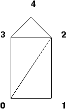
Because Three.js represents everything as triangles, we break up this polygon into three triangles. (Again, this is arbitrary — how many ways can you find to break up the polygon into triangles?) We then define a face (a triangle) by listing its three vertices, in counter-clockwise order from the outside. So, 4,3,2 is one way to describe the top of the barn. The triangles 3,2,4 and 2,4,3 are equivalent, but 2,3,4 is not, because that would say we are currently looking at the back of the triangle. This is important because, by default, Three.js only draws the front of triangles. That is, it skips rendering any back-facing triangles. You can see how that cuts in half the amount of rendering that has to be done, and at very little cost. For example, if we're only going to look at the outside of the barn, there's no reason to ever draw the back side of any of the faces. Now, as it happens, in this demo I have specified to Three.js that the barn faces are two-sided, so that Three.js will render both sides. That way, if you dolly in so that the camera goes inside the barn, you'll be able to see the "other" side. If you use the default, efficient setting of one-sided faces and you get your vertices in the wrong order, those faces will not be drawn — a strange and painful problem to debug.
- Please click that link and then click on
main.html. That will show the demo in your brower. - You can drag the mouse to view it from different directions.
- You can use the GUI to adjust the size of the barn.
Normal Vectors
Each face also has an associated vector that is perpendicular to the face, which mathematicians and computer graphics people call the normal vector. We'll learn that these are crucial in lighting computations.The front of the barn lies in the z=0 plane, because all the z coordinates of its vertices are zero. Therefore, the front of barn has a normal vector that is parallel to the z axis. Take a moment to try to visualize this. You can also try playing with this
visualization of the coordinate axes
to exercise your intuition. Check that the following claims make sense to you:
- The red line marks the X axis.
- The green line marks the Y axis.
- The blue line marks the Z axis.
The Z axis initially points towards you, the viewer. You'll need to move the camera a little to see it — click and drag to move the camera.
More things to notice:
- The axes are all perpendicular to each other. Synonymously, they are all normal to each other.
- The blue vector is the normal vector for the XY plane, which is also the z=0 plane. Similarly, the green vector ("up") is the normal vector for the XZ plane (the "ground"). Finally, the red vector is the normal vector for the YZ plane.
Fortunately, Three.js can compute normal vectors for us. Eventually, we'll learn how to do this as well.
Points and Vectors in Three.js
If we choose a suitable origin and coordinate system (more about origins and coordinate systems later), we can define a point in 3D space with just three numbers. We can also define vectors with just three numbers. Consider the following four objects:
P = (1, 5, 3)
Q = (4, 2, 8)
v = P-Q = (-3, 3, -5)
w = Q-P = (3, -3, 5)
P and Q are points in space. A vector can be thought of as an arrow between two points or even as a movement from one to the other. Therefore, the vector v from Q to P is just P-Q (subtract the three components, respectively). The vector w, from P to Q, is just the negative of vector v. In 3D, both points and vectors are represented as a triple of numbers.
How do we specify points and vectors to Three.js? Here's an example:
let P = new THREE.Vector3(1,2,3);
We won't have to use such low-level code for a while. Note that the
authors of Three.js only defined a Vector3 class, which we'll use
for both points and vectors. However, they are different concepts, so
we will continue to use the term "point" for the locations of vertices
and the term "vector" for directions of rays.
Drawing in Three.js
How do we draw stuff in Three.js? As we know from above, it's a two-step process: we represent something and then we render it. Let's expand on those ideas:
- A geometry is a data structure of vertices and faces and associated geometrical information, such as normal vectors for each face.
- A material is a set of properties that directly or indirectly specify the color of the object. The colors of the faces can be set directly by the material (such as, "this face is red"), or indirectly ("this face interacts with light in the following ways ..."). We'll learn more about materials that interact with light a bit later.
- A mesh is a combination of a geometry and its material, which then has enough information to be rendered.
So, in Three.js, we'll build a geometry object, combine it with some material, and add it to the scene. Later, we'll learn about how scenes are rendered.
Coordinates
Because we're using 3D models, all of our vertices will have 3 components: X, Y, and Z. You can set up your own camera anywhere you want, but initially the camera is such that X increases to the right and Y increases going up. The Z coordinate increases towards you, so things farther from you in the scene have smaller Z components or even negative ones.
In OpenGL/WebGL, our coordinates can have (pretty much) any scale we want. For example, you could have all your X, Y, and Z coordinates be between 0 and 1. Or you could have them all be between 1 and 100. Or between -1000 and +1000. Furthermore, these numbers can mean anything you want, so your coordinates can be in millimeters, kilometers or light years. So if you're imagining a real barn, perhaps the numbers are in feet or meters.
The TW module can set up the camera for you if you tell it the range of your coordinates, called the scene bounding box. (This camera is often a bit too far for good realism, but is helpful for debugging.)
Creating a Simple Scene with Three.js and TW
Three.js has a number of built-in geometries for common objects such as planes, boxes, spheres, and so on. To see how a simple webpage can be constructed that contains graphics created with Three.js and TW, view the source code for this Scene with a Box. That link leads to a folder with two files in it:
main.js, which has the main graphics code. Click on this to see the code.main.html, which will load and run the graphics code. Click on this to run the demo.
Please click through an run the demo and play with the GUI just a bit. Try dragging the mouse as well, to move the camera viewpoint. Then click through and skim through the code. Doing both will make the code review below a bit more intuitive.
Prelude Code
Let's look at the code in main.js in chunks. The first part of the
file is a "prelude" of mostly standard boilerplate code. Let's start
with that.
The first few lines import some libraries (APIs) for us.
//import three js and all the addons that are used in this script
import * as THREE from 'three';
import { TW } from 'tw';
import GUI from 'https://cdn.jsdelivr.net/npm/lil-gui@0.20/+esm';

console.log(`Loaded Three.js version ${THREE.REVISION}`);
The next few lines help us to access these APIs from the JS
console. The variable
globalThis
is a builtin object in JS that exists in all environments
(namespaces). In particular, it's in the JS console in our browser, so
anything we put in globalThis is easily avaible when we are
debugging.
// for debugging
globalThis.THREE = THREE;
globalThis.TW = TW;
We always need a scene object to contain all the objects for the
scene that we want to render. Again, we'll make it available in the
console.
// Create an initial empty Scene
var scene = new THREE.Scene();
globalThis.scene = scene;
Next, we build some objects for our scene. This part of the program is where the bulk of your work will go, as you build objects to be rendered. Let's cover that in the next section
Building the Scene
The heart of our code, between the prelude and the postlude, is where we build the scene. Here it is as a whole:
// ================================================================
// Build your scene here

const box1dims = {width: 2,
                  height: 3,
                  depth: 4};

var box1;

function newBox() {
    scene.remove(box1);
    const geo = new THREE.BoxGeometry(box1dims.width,
                                      box1dims.height,
                                      box1dims.depth);
    const mat = new THREE.MeshNormalMaterial();
    box1 = new THREE.Mesh(geo, mat);
    box1.name = "box1";
    scene.add(box1);
}

newBox();
There are some interesting tricks above:
- Rather than put hard-code scene parameters and constants into our
code (which is poor practice), or even in global variables or
constants (which is better), we put them in a global dictionary
that is the value of
box1dims. That technique allows us to easily create a GUI that lets the user modify the values in the browser, without having to edit the code. We'll see that in a moment. - We create a global variable,
box1, to hold one of our meshes. We don't have to do this and we won't always do it, but we do here. - We define a function,
newboxto build a box and add it to the scene, replacing any prior box. - Then we invoke the function. That's better modularity than just
putting all the code at top-level in the file and also makes it
easier to re-built the scene after adjusting the parameters
(
box1dims)
Building a Mesh
Before we go on, let's zoom in on the process of building a mesh, from
the newBox function above:
    const geo = new THREE.BoxGeometry(box1dims.width,
                                      box1dims.height,
                                      box1dims.depth);
    const mat = new THREE.MeshNormalMaterial();
    box1 = new THREE.Mesh(geo, mat);
    box1.name = "box1";
    scene.add(box1);
The first statement creates an instance of a THREE.BoxGeometry,
supplying 3 arguments to specify the width (x-dimension), height
(y-dimension) and depth (z-dimension) of the box. All the Threejs
geometries are reasonably well documented, often with demos, and you
are encouraged to read the documentation: THREE.BoxGeometry
The second statement creates a material, in this case an instance of
THREE.MeshNormalMaterial. That material would rarely be used in a
real scene, but is great for demonstration purposes, because each face
of an object gets a color that depends on its orientation (surface
normal). For example, the right face (surface normal of [1,0,0]) of a
box might be red, while the top (surface normal of [0,1,0]) might be
green, etc. The documentation
THREE.MeshNormalMaterial.
The third statement combines the two into a THREE.Mesh, as we
described above. Meshes have different methods than geometries and
materials. For example, there are methods to move and rotate meshes,
which we'll get into soon. Documentation on THREE.Mesh
We assign a name to the mesh, but this is totally optional. In large scenes with lots of meshes, it can be helpful to have names to tell one from another in the debugger.
Creating a mesh doesn't automatically add it to the scene. So, we do that last.
Postlude Code
After defining and invoking newBox to create add a box to our scene,
we come to some "postlude" code that will bring us to the end of
main.js.
First, we have some boilerplate code that creates a renderer and initializes some stuff. TW simplifies this a little.
// ================================================================

// Create a renderer to render the scene
var renderer = new THREE.WebGLRenderer();

// TW.mainInit() initializes TW, adds the canvas to the document,
// enables display of 3D coordinate axes, sets up keyboard controls
TW.mainInit(renderer,scene);
Next, we create a GUI so that the user can adjust the box dimensions that we put in a global dictionary.
const gui = new GUI();
gui.add(box1dims, 'width', 1, 10).onChange(newBox);
gui.add(box1dims, 'height', 1, 10).onChange(newBox);
gui.add(box1dims, 'depth', 1, 10).onChange(newBox);
Finally, we set up a camera. Cameras are more complicated than this, but we'll put off learning the Threejs camera API for a few weeks. Meanwhile, we'll have TW set up a simple camera for us, just by saying roughly where our stuff is (the range of x, y and z coordinates).
// Set up a camera for the scene
var state = TW.cameraSetup(renderer,
                           scene,
                           {minx: -5, maxx: 5,
                            miny: -5, maxy: 5,
                            minz: -5, maxz: 5});
That's it!
Code Summary
To recap, the key elements include:
- a
THREE.Sceneobject that is a container used to store all the objects and lights for the scene we want to render - a JS dictionary of dimensions for the box
- a global variable that holds a box (mesh)
- a function
newBoxthat- removes the current box from the scene,
- builds a new one using the dimensions in the dictionary
- adds it to the scene
- a call to that function to build a box when the page loads
- a
WebGLRenderer - some graphical user interface magic that builds widgets to allow you
to adjust the box dimensions and invoke
newBoxto replace it. TW.cameraSetupthat automatically sets up a camera for you. The arguments to that function specify the range of x, y and z coordinates and sets up a camera that will view those.
You can make much more complex scenes by adding more meshes to the
scene object.
The Barn Code
The barn code is intentionally very similar. If you want to see it, it is in barn demo. Again, please click through and play with it a bit.
The key difference is that we use a couple of helper functions in TW
to build the object, rather than classes in THREE.
    const geo = TW.barnGeometry(box1dims.width,
                                box1dims.height,
                                box1dims.depth);
    box1 = TW.createMesh(geo);
It's similar: we still create a geometry and a mesh. The code using TW
doesn't use new and we haven't specified a material. The material is
created by TW.createMesh, and uses THREE.MeshNormalMaterial, as
our box did.
Three.js Fundamentals
You are strongly encouraged to read the beginning of this page on fundamentals of Three.js, at least up to the part about cameras. We'll get to cameras soon enough.
Learning More Three.js
We'll learn much more Three.js over the semester, and most of what you need to know will be covered in the online readings and lecture notes for the course. Other sources include:
- Book by Jos Dirksen, Learn Three.js — Third Edition. (The fourth edition is out and will be better for newer Three.js code.)
- Three.js documentation](https://threejs.org/docs/index.html#manual/introduction/Creating-a-scene) — this is more of a reference source than a tutorial, but includes many code examples and links to the Three.js source code on GitHub. The online CS307 course notes contain many links to specific documentation pages.
Summary
- An API is a set of programming "things" (functions, classes, variables) that add functionality to our program. CS 307 uses three:
- Threejs (this is the lion's share)
- WebGL/OpenGL (a little of this, mostly later in the course)
- TW (a handful of useful helper functions
- Modeling: specifying the geometry of an object and also its material
- Rendering:
- using a camera (and possibly other stuff like lights), determine what an object looks like
- converts to pixels (a raster representation)
- Pipeline:
- lots of information is not retained
- render, adjust, re-render
- Geometry Data structures
- Points/Vertices: locations in 2D (x,y) or 3D (x,y,z)
- Vectors: directions, specified in 2D (dx, dy) or 3D (dx, dy, dz)
- Line Segments: lines with endpoints
- Triangles: very important in CG, because they are necessarily flat and convex
- polygons: broken up into triangles
- polyhedra: the surfaces are broken up into triangles
- Triangles: have a front and a back.
- Typically, the front is the where the vertices are in counter-clockwise order
- Normal vectors:
- vectors perpendicular to a surface
- we'll get to these soon, but not yet
- Program structure:
- An HTML file that specifies the JS file(s) to load
- A
main.jsfile that has- a
sceneobject that contains all the meshes - the meshes
- a
rendererobject - a camera setup. We'll use TW for that for now
- a