Reading on WebGL
The two best books I've found (so far) are:
- WebGL Programming Guide: Interactive 3D Graphics Programming with WebGL by Kouichi Matsuda and Rodger Lea
- WebGL Beginner's Guide by Diego Cantor and Brandon Jones
I found the Cantor and Jones book first and have more experience with it, so we'll use their examples. I also like their way of writing down the shaders within the browser. Nevertheless, the Matsuda and Lea book is well written and their code has some nice libraries as well.
You aren't a beginner graphics programmer, but these books are for beginners with WebGL, so we'll still find them instructive even though the first programms are quite simple.
SIMD Programming
There are few ideas that we have to start with. Modern graphics programming is done by, in part, writing shaders. These are programs that run in processing elements on the graphics card. Each processing element is kinda like the CPUs (processors) that you learn about in CS 240, except that there are many of them. A modern graphics card will have lots of these processing elements (say, 300+). Thus, these programs are running in parallel. FYI, each processing element is sometimes called a PE for short.
One of the fundamental ways that parallel processing can be done in
computers is called SIMD,
for single instruction, multiple
data
. The idea is that there is a single program, and each PE is
running that same program at the same time, but each one has its own
data. So, at each moment, a single instruction is being executed, but on
multiple data.
Imagine you have to do some tedious calculation, such as computing
$3x^2+4x+5$ for all $x \in [1..25]$. Fortunately, you have 25 helpful
friends, so you get them all in a room, hand them the calculation
algorithm, and give each of them a different value for $x$. You can
even synchronize their actions, such as calling out square $x$
and so forth. A little while later, you have all 25 values
computed. This is perfect parallelism.
Finding real-world problems where we can have that perfect SIMD parallelism can be hard in practice, and fitting the number of PEs to the problem can be imperfect. (If you have 26 willing friends, one of them has nothing to do; if you only have 24 willing friends, it'll take you twice as long to get 25 results as it takes you to get 24 results, and on the second round, 23 of your friends are idle.)
However, in computer graphics, we almost have that situation. Each fragment (pixel) can be computed in parallel. My friend Martin Herbordt at BU gave a talk at Wellesley a few years ago, in which he described exploiting this parallel processing hardware to solve real-world problems like matrix multiply by recasting the problem as a graphics computation. People are using graphics cards as super-computers to do machine learning using tensorflow as well as less socially useful computations such as mining bitcoins and cracking passwords.
Pipelining
There's another kind of parallelism that the graphics card uses, namely pipelining. This is the same kind of pipelining that a CPU uses, as you learned in CS 240. The idea is breaking a computation down into stages, so that the output of one stage is the input to the next. This is important when one thing depends on another, so you can't compute them in parallel, as we did in the previous example of computing 25 values of a polynomial.
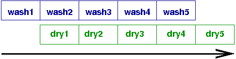
Instead, consider an example that happens to me pretty much every
weekend. I have to do, say, 5 loads of laundry. The washing machine
takes about 40 minutes, and the dryer takes an hour or so. For
simplicity, let's suppose they each take an hour. So, it seems like I
have $5\times2=10$ hours of laundry to do. But that's idiotic, because
it has no parallelism. Instead, I can do it in 6 hours, by putting the
first load in the dryer, while the second load is in the washer, and so
forth:
Pipelining is sometimes called vertical
parallelism in contrast
to the horizontal
parallelism earlier, where we spread the
computation over a bunch of PEs, all at the same time.
Pipelining in OpenGL
Please read the following page on the the OpenGL pipeline. It's just a bit over 2 printed pages long.
In OpenGL/WebGL, there are two parts of the pipeline that are custom programmable by the user:
- the vertex shader. The output of the vertex shader stage of the pipeline includes the position of the vertex.
- the fragment shader. The output of the fragment shader stage of the pipeline includes the color of the vertex.
A fragment
is the data necessary to generate a single pixel in the framebuffer.
So, wherever we say fragment
, you can think pixel
.
Buffers
The shaders that we will write need to have all the data available to them. For example, the vertex shader needs to know things like the vertex's (x,y,z) location and the locations of light sources. The fragment shader needs to know things like the texture coordinates, since texture-mapping is done in the fragment shader.
OpenGL in principle supports two different modes
:
- Immediate mode: render stuff as it is sent from the main processor down to the graphics card
- Retained mode: render stuff that has already been sent to the
graphics card and is stored in local memory of the card, sometimes
called
buffers
However, one of the things that has happened in the last decade, since OpenGL 3.0, is that the immediate mode is deprecated. Don't use it anymore. The reason is performance. If you're rendering a scene with a million triangles, not to mention textures and such, you don't want to repeatedly send that stuff down to the card. Instead, you want to have it already sitting there, ready for the rendering pipeline.
Consequently, we now have to write code that fills buffers with data, including position data (x,y,z), as well as normals, material, texture coordinates, and all sorts of other stuff. Three.js manages this for us. Without Three.js, we have to think about that stuff.
Shaders
We also have to write vertex shaders and fragment shaders. Shaders are written in another language, the OpenGL Shading Language, GLSL. GLSL looks a lot like the C programming language, but really is its own language, with special features for the kind of programming that needs to be done.
For example, there is special support for creating 2, 3, and 4-place vertices and vectors, and special notation for computing dot products and cross products. We'll see some examples.
Because the language runs on the PEs on the graphics card, debugging
isn't easy. There are no print statements and no
single-stepping debuggers.
There are two new categories of variables:
- uniform for values that are the same from one vertex to another, or from one fragment to another, and
- varying for values that differ from one vertex to another or from one fragment to another. (This is the multiple data of our SIMD parallelism.)
We'll see examples of these as we look at the code for some examples of WebGL programming.
Square
Here's a very simple, but complete, example from Cantor and Jones. It just draws a single square. I've omitted the sophisticated display code they have, to focus on the essentials.
Square example from chapter 2 of Cantor and Jones
Vertex Shader
// vertex shader. Position is unchanged
attribute vec3 aVertexPosition;

void main(void) {
     gl_Position = vec4(aVertexPosition,1.0);
}
The vertex shader makes use of a buffer
called aVertexPosition that contains an attribute of the
vertex, namely its position, as a 3-place vector. The vec4
function returns a 4-place vector (in homogeneous coordinates),
supplying a 1 for the fourth place.
The output of this stage is the position of the vertex,
in gl_Position.
Fragment Shader
Here's the fragment shader:
// fragment shader. Every pixel is teal
#ifdef GL_ES
precision highp float;
#endif
void main(void) {
    gl_FragColor = vec4(0.5,0.5,1.0, 1.0);
}
The fragment shader ignores any attributes of the fragment and just
makes the pixel a particular shade of blue, close to light sky blue. The
output is a vec4 because of the alpha or opacity channel.
HTML
Next, let's look at the HTML, which is quite minimal, except for one
clever trick they use, which is to put the vertex and fragment shaders
in the HTML file, in a script element with a type attribute
that is not text/JavaScript, so the browser will ignore
it. However, we'll see that the JS code can extract the contents of
these elements and compile and use them as shaders.
<html>

<head>
<title>WebGL Beginner's Guide - Chapter 2 - Rendering a Square</title>
<!-- minimal version of the Diego Cantor & Brandon Jones example.
     Boiled down by Scott D. Anderson -->

<!-- JavaScript Libraries //-->
<script type='text/javascript' src='utils.js'></script>

<!-- Fragment Shader //-->
<script id="shader-fs" type="x-shader/x-fragment">
    #ifdef GL_ES
    precision highp float;
    #endif
    void main(void) {
        gl_FragColor = vec4(0.5,0.5,1.0, 1.0);
    }
</script>

<!-- Vertex Shader //-->
<script id="shader-vs" type="x-shader/x-vertex">
        attribute vec3 aVertexPosition;

        void main(void) {
                gl_Position = vec4(aVertexPosition,1.0);
        }
</script>

<script id="code-js" type="text/javascript">

  // omitted for now
</script>
</head>

<body onLoad='runWebGLApp()'>
<div id='top'>
    <h1>WebGL Beginner's Guide - Chapter 2</h1>
    <h2>Rendering a Square</h2>
    <div id='logo-packt'><img src='packt.gif'/></div>
    <p>WebGL uses buffers to store and process vertex and index
data. The mechanism is the same whether we are rendering
a simple object like a square or a racing car as we will see later on.
</p>
</div>

<div id='contents'>
        <div id='canvasContainer'>
                <canvas id='canvas-element-id' width='480' height='400'>
                        Your browser does not support the HTML5 canvas element.
                </canvas>
        </div>
</div>

</html>
There's nothing too surprising here. There's the basic HTML template, the two shaders, some JavaScript code (omitted) that actually does all the work, and a canvas that displays the rendered scene.
The pages uses an onload event handler to execute
the runWebGLApp function that starts the whole ball rolling.
JavaScript
Finally, let's turn to the JS code. Cantor and Jones did a pretty good job of commenting this, so you should be able to understand most of this. Bring questions to class!
var gl = null; // WebGL context
var prg = null; // The program (shaders)
var c_width = 0; // Variable to store the width of the canvas
var c_height = 0; // Variable to store the height of the canvas

var squareVertexBuffer = null; //The vertex buffer for the square
var squareIndexBuffer = null; // The index buffer for the square

var indices = []; // the indices of the square
var vertices = []; // the vertices of the square

/*
 * The program contains a series of instructions that tell the
 * Graphic Processing Unit (GPU) what to do with every vertex
 * and fragment that we pass it. (more about this on chapter 3)
 * The vertex shader and the fragment shader together are called
 * the program.
 */

function initProgram() {
    var fgShader = utils.getShader(gl, "shader-fs");
    var vxShader = utils.getShader(gl, "shader-vs");

    prg = gl.createProgram();
    gl.attachShader(prg, vxShader);
    gl.attachShader(prg, fgShader);
    gl.linkProgram(prg);

    if (!gl.getProgramParameter(prg, gl.LINK_STATUS)) {
        alert("Could not initialise shaders");
    }

    gl.useProgram(prg);

    // The following lines allow us obtaining a reference to the
    // uniforms and attributes defined in the shaders.  This is a
    // necessary step as the shaders are NOT written in JavaScript
    // but in a specialized language called GLSL. More about this
    // on chapter 3.
    prg.vertexPosition = gl.getAttribLocation(prg, "aVertexPosition");

}

   /*
    * Creates the buffers that contain the geometry of the square
    *
    *   #0 (-0.5,0.5) +--------------+  (0.5,0.5)  #3
    *                 |              |
    *                 |              |
    *                 |      .(0,0)  |
    *                 |              |
    *                 |              |
    *   #1(-0.5,-0.5) +--------------+  (0.5,-0.5) #2
    */

function initBuffers() {

    vertices =  [
            -0.5,0.5,0.0,   //Vertex 0
            -0.5,-0.5,0.0,  //Vertex 1
            0.5,-0.5,0.0,   //Vertex 2
            0.5,0.5,0.0];   //Vertex 3

    indices = [3,2,1,3,1,0];

    //The following creates a vertex buffer and binds the vertices to it
    squareVertexBuffer = gl.createBuffer();
    gl.bindBuffer(gl.ARRAY_BUFFER, squareVertexBuffer);
    gl.bufferData(gl.ARRAY_BUFFER, new Float32Array(vertices), gl.STATIC_DRAW);
    gl.bindBuffer(gl.ARRAY_BUFFER, null);

    //The following creates a vertex buffer and binds the indices to it
    squareIndexBuffer = gl.createBuffer();
    gl.bindBuffer(gl.ELEMENT_ARRAY_BUFFER, squareIndexBuffer);
    gl.bufferData(gl.ELEMENT_ARRAY_BUFFER, new Uint16Array(indices), gl.STATIC_DRAW);
    gl.bindBuffer(gl.ELEMENT_ARRAY_BUFFER, null);
}

/**
 * Draws the scene
 */

function drawScene() {
    gl.clearColor(0.0, 0.0, 0.0, 1.0);
    gl.enable(gl.DEPTH_TEST);

    gl.clear(gl.COLOR_BUFFER_BIT | gl.DEPTH_BUFFER_BIT);
    gl.viewport(0,0,c_width, c_height);

    gl.bindBuffer(gl.ARRAY_BUFFER, squareVertexBuffer);
    gl.vertexAttribPointer(prg.aVertexPosition, 3, gl.FLOAT, false, 0, 0);
    gl.enableVertexAttribArray(prg.vertexPosition);

    gl.bindBuffer(gl.ELEMENT_ARRAY_BUFFER, squareIndexBuffer);
    gl.drawElements(gl.TRIANGLES, indices.length, gl.UNSIGNED_SHORT,0);
}

/**
 * Render Loop
 */
function renderLoop() {
    utils.requestAnimFrame(renderLoop);
    drawScene();
}

/**
 * Executes the WebGL application
 * This function is invoked on the onLoad event of the webpage.
 */
function runWebGLApp() {
    //Obtains a WebGL context
    gl = utils.getGLContext('canvas-element-id');
    //Initializes the program (shaders). More about this on chapter 3!
    initProgram();
    //Initializes the buffers to draw the square (vertex buffer and index buffer)
    initBuffers();
    //Renders the square!
    renderLoop();
}
A few things to note:
- Cantor and Jones have some utilities (loaded
from
utils.js) that do useful, generic things, but the most important one isgetShader, which:- takes the ID of an element in the document, such as
shader-fs - extracts the textual content of that element, which is the shader source code
- creates a shader object using the GL context,
- compiles the shader source code into that shader object, and
- returns the shader object.
- takes the ID of an element in the document, such as
- The buffer arrays have datatypes, as in C, such as a 32-bit float
(
Float32Array) or a 16-bit unsigned integer (Uint16Array). - All the drawing is done by just one call,
namely,
gl.drawElements; everything else is setup!
Material and Lighting
That's a nice, warm-up example, but the shaders are a little disappointing in their simplicity. To close this reading, I'll show you some more complex shaders that use material and lighting.
Here's the vertex shader:
attribute vec3 aVertexPosition;
attribute vec3 aVertexNormal;

uniform mat4 uMVMatrix;
uniform mat4 uPMatrix;
uniform mat4 uNMatrix;

uniform vec3 uLightPosition;

varying vec3 vNormal;
varying vec3 vLightDir;
varying vec3 vEyeVec;

void main(void) {

 //Transformed vertex position
 vec4 vertex = uMVMatrix * vec4(aVertexPosition, 1.0);

 //Transformed normal vector
 vNormal = vec3(uNMatrix * vec4(aVertexNormal, 0.0));

 //Light position
 vLightDir = vertex.xyz - uLightPosition;

 //Vector Eye
 vEyeVec = -vec3(vertex.xyz);

 //Final vertex position
 gl_Position = uPMatrix * uMVMatrix * vec4(aVertexPosition, 1.0);

}
And here's the fragment shader. Notice the implementation of the Phong model:
#ifdef GL_ES
precision highp float;
#endif

uniform float uShininess;        //shininess
uniform vec4 uLightAmbient;      //ambient color
uniform vec4 uLightDiffuse;      //light color
uniform vec4 uMaterialDiffuse;   //object color

varying vec3 vNormal;
varying vec3 vLightDir;
varying vec3 vEyeVec;

void main(void)
{
 vec3 L = normalize(vLightDir);
 vec3 N = normalize(vNormal);

 //Lambert's cosine law
 float lambertTerm = dot(N,-L);

 //Ambient Term
 vec4 Ia = uLightAmbient;

 //Diffuse Term
 vec4 Id = vec4(0.0,0.0,0.0,1.0);

 //Specular Term
 vec4 Is = vec4(0.0,0.0,0.0,1.0);

 if(lambertTerm > 0.0) //only if lambertTerm is positive
 {
  Id = uMaterialDiffuse * lambertTerm; //add diffuse term

  vec3 E = normalize(vEyeVec);
  vec3 R = reflect(L, N);
  float specular = pow( max(dot(R, E), 0.0), uShininess);

  Is = uLightDiffuse * specular; //add specular term
 }

 //Final color
 vec4 finalColor = Ia + Id + Is;
 finalColor.a = 1.0;

 gl_FragColor = finalColor;
}
In class, we'll look at more of Cantor and Jones's examples, and also some shaders written by Three.js