Assignment 7
Part I
Due: Thursday,
November 15
|
|
CS 332
Assignment 7
Due: Thursday, |
|
This first part of Assignment 7 contains one problem that involves a hand simulation of Ullman's incremental rigidity scheme for recovering 3-D structure from motion, and second programming problem in which you will create an interesting 3-D motion display and learn how to create movies in MATLAB.
Part a: Hand simulate the behavior of Ullman's Incremental Rigidity Scheme for three points undergoing a rotation in depth. Assume that the vertical position of each point in the image is the same. The initial horizontal position of the points, and their initial true placement in depth, is shown in the following bird's eye view:
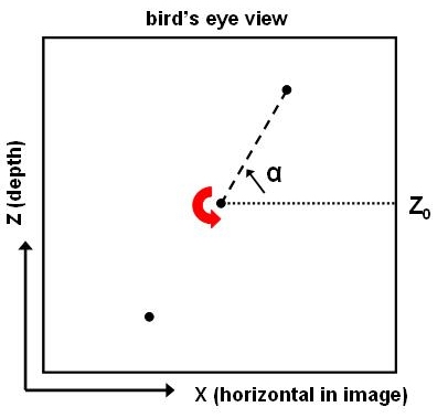
Assume that over time, the two outer points rotate around the center point in the counterclockwise direction. Also assume that the 3-D position of the center point is known to the algorithm (i.e. it is known to be located at depth Z0, as shown above). The center point does not move over time. For the initial position of the points, the angle α shown above is 60°. In your hand simulation, first draw a picture of the initial 3-D model with which the Incremental Rigidity Scheme begins. Then rotate the true points in discrete steps, by an angle of 20° per step, for a total of 200° of rotation (10 steps altogether). Draw a bird's eye view of the new 3-D model that is computed by the algorithm for each new image view of the points. At each time step, the x coordinates of the two moving points are given by their position in the projected image (assume orthographic projection), and you should determine the two new z coordinates that would be computed by the algorithm. This determination can be done geometrically, similar to the two exercises that we completed in class. You do not need to perform any numerical calculations. Also summarize in words, how the 3-D structure of the points evolves over the 10 steps of the simulation.
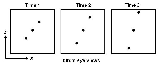
Part b: Suppose that the distance between the two outer points were to increase at a constant rate while they are rotating, as suggested by the three frames below. Over an extended time period (i.e. over multiple revolutions of the points), would the Incremental Rigidity Scheme always be able to derive the correct 3-D structure at every moment?
Part c: When introducing the rigidity assumption, I briefly described the nature of early theoretical results that addressed the following question: What is the minimum amount of information that must be integrated in the changing image, in order to compute a unique interpretation of the 3-D structure of a moving object, assuming that the object is rigid? For example, I noted the following result from Ullman's work:
Given 3 distinct orthographic views of 4 non-coplanar points in motion, if there exists a rigid 3-D structure consistent with these views, then this structure is unique.
Consider the example used in Part a, consisting of two points rotating around a central point whose position is known, as shown below (the dashed circle shows the complete path of the two points over their full rotation):
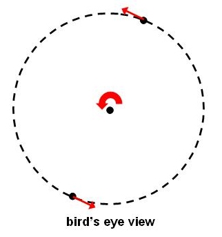
In class, it was noted that when the human visual system views three points in motion like this, the points are seen as following a circular path in space, similar to the true motion shown above. Ullman's result summarized above, however, suggests that in theory, this solution may not be unique - there may be multiple rigid configurations of three points in motion that are consistent with the changing image that is produced in this case. In fact, there is an infinite set of possible configurations of three points moving rigidly over time that would produce the same changing image as that produced by the circular motion illustrated above. First, generate at least two examples of moving points that would produce the same changing image. Assume for each example, that the central point stays at a fixed position over time, and that this position is known. Also, the examples must differ in their bird's eye view. You should not include depth reversals in your answer. Second, you now know from your analysis in Part a that the Incremental Rigidity Scheme derives a unique 3-D structure in this case. It follows that the Incremental Rigidity Scheme must be using more than just the rigidity constraint in order to derive a unique solution, given that there are infinitely many rigid structures that are consistent with the projected image motion. Where does this additional constraint come from? In other words, why does the algorithm end up computing the particular rigid solution that it did in your analysis for Part a?
If an object simply undergoes pure rotation in the image plane, it does not generate 2-D
image motion that can be used to recover its 3-D shape. There are some patterns, however,
that yield a percept of 3-D shape when they are just rotating rigidly in the image. A
particularly striking example of such a pattern is shown below. A movie of this pattern
rotating can be found at a website developed by Michael Bach
(http://www.michaelbach.de/ot/mot_ske/index.html).
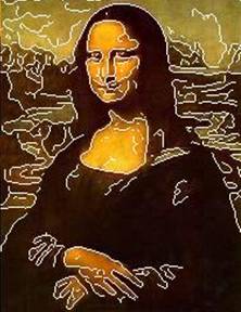
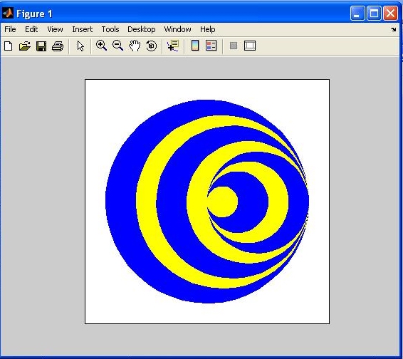
This phenomenon is known as the stereokinetic effect. In this problem, your first step will
be to write a MATLAB function named ske that creates a movie of the pattern shown
below, rotating around its center. This function can be implemented in a way that allows you to
create a variation on this pattern that highlights the basis for perceiving 3-D shape from this
moving image.
To begin, download the /home/cs332/download/ske folder from the CS file server
and set your Current Directory in MATLAB to this folder. There are three functions contained in
this folder. The function circlePoints generates x,y coordinates of
a set of points evenly spaced around a circle. The inputs to this function are the
x,y coordinates of the center of the circle, the radius of the circle, and
the number of sample points around its perimeter. This
function returns two vectors containing the x and y coordinates.
The rotatePoints function rotates the input x,y coordinates around
the origin by the input angle (specified in degrees), and returns a new set of x
and y coordinates stored in vectors. Finally, the makeMovie function
creates a movie of a circle rotating in the image. The movie is a sequence of frames stored in
a vector of MATLAB structures. This function uses two built-in functions, fill
and getframe. The fill function draws a filled-in
polygon, given the x and y coordinates of points around its
perimeter. The getframe function creates a snapshot of the picture displayed in the
current figure window. The built-in movie function can then be
used to display the frames of the movie. The inputs to movie are a vector of structures
containing the movie frames, the number of times to show the movie, and the rate of presentation
of the frames, specified as the number of frames per second. The makeMovie and
movie functions can be called as shown below:
    >> circleMovie = makeMovie;

    >> movie(circleMovie, 2, 10);
Look carefully at each of the functions defined in the ske folder. Then define
a function named ske with the following header:
function movieFrames = ske (npts)
The input npts specifies the number of points around the perimeter of
each circle in the pattern. A value of 50, for example, will create a smooth circle. Your
ske function should return the frames of a movie in which the above pattern
is rotated around its center (for simplicity, the largest blue circle should be centered
at the origin, (0,0)). The pattern can be rotated around its center in
10° steps, as illustrated in the makeMovie function. Feel free to change
the colors in the pattern - it is easiest to use the 8 basic colors that can be specified
with a single character (r(red), g(green), b(blue), m(magenta), c(cyan), y(yellow),
w(white) and k(black)).
When your ske function is complete, create a movie with a much smaller
value for the input npts. The pattern below was created with npts=10,
but you can try smaller values. Do you still have a strong perception of 3-D shape in this
case?
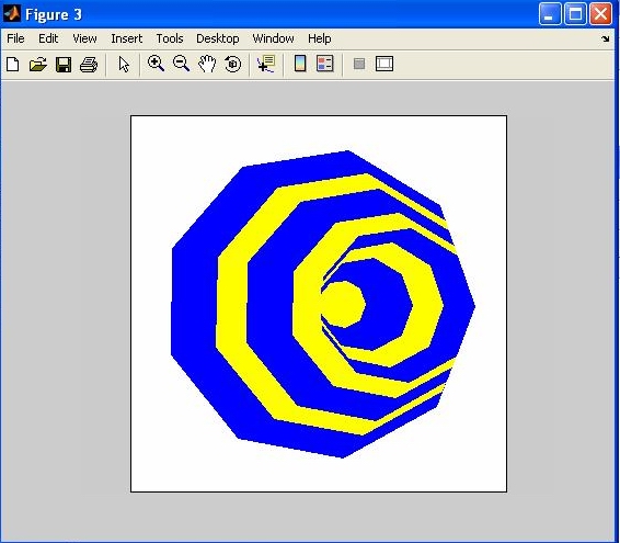
Researchers have argued that we perceive 3-D shape in stereokinetic displays because we actually derive an incorrect percept of the 2-D motions of the figures within the pattern. Consider one of the large inner circles in the original pattern above that is composed of smooth circles. In one picture, draw the two positions of this circle at two nearby moments in time. Select a few sample points around the circle and connect the corresponding points in the two frames (assuming that the original pattern is rotating around its center). Now watch the movie carefully and try to determine how the points in these two frames appear to correspond in our percept of the image motion. The correspondence of points will differ in this case - make a new drawing that conveys our perceived motion of points between the two frames that you selected. Try to explain why we see a rigid 3-D shape in motion for this pattern, given our incorrect perception of the image motion. Note that in the second pattern shown above, consisting of polygons with distinct corners, we perceive the 2-D image motion of the inner figures correctly.
Submission details: Hand in a hardcopy of your ske.m
code file and your answers to the questions in Problems 1 and 2.
Please also hand in an electronic copy of the ske.m
code file by posting a message to the CS332-F07 Drop conference with
this code file as an attachment.