Camera API
There are two aspects to the camera API: the placement of the camera, and the shape of the camera. To understand the latter, we need to understand how cameras work.
The Pinhole Camera
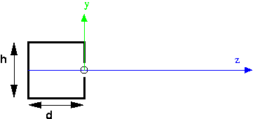
This is a cutaway side view of a pinhole camera (in Latin, the "camera obscura," which means "dark room"). The z axis is imaginary, but the box on the left part of the picture is a real box: solid on all six sides. There is a tiny pinhole in the front of the box, where the circle is on the picture. The origin is placed at the pinhole, the y axis goes straight up through the front of the box, and the z axis points out into the scene. The location of the pinhole is also referred to as the focal point. The depth of the box is d, and the height of the box is h. We also might care about the width of the box, but that's not visible in this picture, since we've eliminated that dimension.
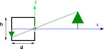
Rays of light from the outside go through the hole and land on the image plane, which is the entire back of the box. For example, a ray of light from the top of the tree lands on the back of the box as shown. Because the hole is so tiny, only light from along a single ray can land on any spot on the back of the camera. So, in this example, only light from the top of the tree can land at that spot. This is why pinhole camera pictures are so sharp. Theoretically, they can provide infinite clarity, though in practice other issues arise (diffraction of light rays and the lack of enough photons). However in computer graphics, we only need the theoretical camera.
Pinhole cameras are simple and work really well. They're standard equipment for viewing solar eclipses. We only use lenses so that we can gather more light. A perfect pinhole camera only really allows one ray of light from each place in the scene, and that would make for a really dark image, or require very sensitive film (or retinas). Since the need to gather enough light is not important in computer graphics, the OpenGL model is of a pinhole camera.
Points to notice:
- The projection of an image (such as the tree) can be computed using similar triangles, as described in the next section.
- The effects of perspective are manifest, such as objects getting smaller in the image with distance from the camera.
- Parallel lines seem to converge at a "vanishing point" (imagine looking down railroad tracks).
- One disadvantage of a pinhole camera is that the image is upside down on the film. (Your SLR camera has "through the lens" viewing, but uses additional lenses to flip the image right side up.) We'll see how to address this soon.
Computing Projection by Similar Triangles
Suppose we want to compute the projection of the top of the tree. Let the coordinates of the top of the tree be $(X,Y,Z)$. We want to know the coordinates of the projection, let them be $(x,y,z)$. We can do this by similar triangles, using the two yellow triangles in the following figure:
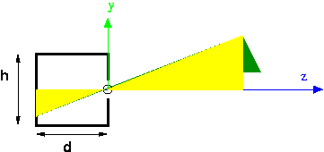
The height and base of the big triangle are just $Y$ and $Z$. The height and base of the little triangle are $y$ and $z$. The base of the little triangle is known, because that's determined by the shape and size of our pinhole camera. In the figure, it's notated as "d." By similar triangles, we know: \[ y/d = Y/Z \\ y = d*Y/Z \\ y = Y/(Z/d) \]
Everything on the right hand side is known, so we can compute the projection of any point simply by knowing the depth of our pinhole camera and the location of the point.
By the way, the reason we do this last algebraic step of dividing by $Z/d$ is because of the way we will use this in our projection matrix.
Projecting the $X$ coordinate works the same way.
The Synthetic Camera
There's a hassle with signs in the pinhole camera, such as whether the $z$ value for the tree is negative. Also, the image ends up being upside down. In CG, since we're really only interested in the mathematics of projection, we use a synthetic camera, in which the image plane is placed on the same side of the origin as the scene.
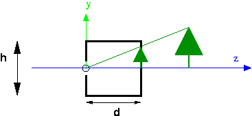
- In CG, we can put the image plane in front of the focal point. This means the image is right side up.
- Mathematically, we'll make the origin be the focal point, with the camera pointing down the negative z axis.
- The image plane is the top of a frustum (a truncated pyramid). See the demo below.
- The frustum is also our view volume. Anything outside the view volume is "clipped" away and not visible in the rendered image.
- Note that this also means that the CG system can't see infinitely far. That's because it needs to calculate relative depth, and it can't make infinitely fine distinctions.
- The projection is computed using a projection matrix.
- Note that there is also an option of doing parallel projection rather than perspective projection. In parallel projection, the rays of light from the scene to the image are drawn in parallel, rather than converging at a focal point. Parallel projection is useful in architectural drawings and the like. We will rarely use it.
Demo: Frustum
The view volume
of the synthetic (perspective) camera is
a frustum: a truncated rectangular pyramid. Follow this
link to a demo that illustrates the frustum and some associated parameters
and terminology:
Demo: Camera
It's easier to understand the power of the camera parameters when we can compare the geometry of the frustum with the resulting rendering of the scene. In the following demo, we see a scene with a teddy bear and a camera, and the rendered result:
Perspective Matrices and Perspective Division
For the same reason that we want to perform all of our affine transformations using matrix multiplication, we want to perform projection using matrix multiplication.
There are two kinds of projection available in OpenGL and Three.js, orthographic and perspective:
- Orthographic (Parallel). With this kind of projection, the view
volume is a rectangular box, and we project just by squeezing out one
dimension. As we mentioned earlier, this kind of projection is useful for
architectural drawings and situations where there really isn't any
perspective. If we align the direction of projection (DOP) with the Z
axis, this kind of projection amounts to setting the Z coordinate of all
points to zero. If we again let the scene coordinates be $(X,Y,Z)$ and projected
coordinates be $(x,y,z)$, here's how orthographic projection can be expressed
as multiplication by a projection matrix:
\[
\vecIV{x}{y}{z}{1} =
\left[
\begin{array}{rrrr}
1 & 0 & 0 & 0 \\
0 & 1 & 0 & 0 \\
0 & 0 & 0 & 0 \\
0 & 0 & 0 & 1
\end{array}
\right]
\vecIV{X}{Y}{Z}{1}
\]
In this case, $x=X$, $y=Y$, and the $z$ coordinate is $0$ for all points.
- Perspective. With this kind of projection, if we set up a frame where the origin is the center of projection (COP) and the image plane is parallel to the Z $=0$ plane (the XY plane), we can compute the projection of each point using the similar triangles calculation, dividing each $Y$ and $X$ coordinate by $Z/d$.
The matrix for perspective projection isn't obvious. It involves using homogeneous coordinates and leaving part of the calculation undone.
The part of the calculation that is left undone is called perspective division. The idea is that the homogeneous coordinate $(x, y, z, w)$ is the same as $(x/w, y/w, z/w, 1)$, that is, we divide through by $w$. If $w=1$, this is a null operation that doesn't change our ordinary vertices. If, however, $w$ has the value $Z/d$, this perspective division accomplishes what we did earlier in our similar triangles, namely: \[ y = Y/(Z/d) \]
Therefore the perspective matrix is a matrix that accomplishes setting $w=Z/d$ and leaves the other coordinates unchanged. Since the last row of the matrix computes $w$, all we need to do is put $1/d$ in the Z column of the last row. The perspective projection matrix, then, is just the following matrix: \[ \left[ \begin{array}{rrrr} 1 & 0 & 0 & 0 \\ 0 & 1 & 0 & 0 \\ 0 & 0 & 1 & 0 \\ 0 & 0 & 1/d & 0 \end{array} \right] \]
Let's consider how this matrix transforms an arbitrary point, $(X,Y,Z)$: \[ \vecIV{x}{y}{z}{w} = \left[ \begin{array}{rrrr} 1 & 0 & 0 & 0 \\ 0 & 1 & 0 & 0 \\ 0 & 0 & 1 & 0 \\ 0 & 0 & 1/d & 0 \end{array} \right] \vecIV{X}{Y}{Z}{1} \]
In this case, $x=X$, $y=Y$, $z=Z$, and $w=Z/d$. To transform the result into a vector with \( w=1 \), we do the perspective division step, namely we divide all the components by \( Z/d \), yielding: \[ \vecIV{x/(Z/d)}{y/(Z/d)}{z/(Z/d)}{1} = \frac{1}{Z/d} \vecIV{x}{y}{z}{Z/d} \]
This is exactly the point we want, namely the projection of the original point onto an image plane at a distance of \( d \).
Here's a PDF document that gives the math for projection.
Perspective Cameras in Three.js
As illustrated in the earlier frustum and Camera API demos, in Three.js, we can set up a perspective camera like this:
var camera = new THREE.PerspectiveCamera(fov,aspect_ratio,near,far);
We'll think of this API as setting up the camera shape (the geometry of the frustum).
As we saw above, the perspective and orthographic projections work when the axis is aligned with the Z axis. This is actually the same as the initial coordinate system in OpenGL. But what if we don't want our scene/camera set up this way?
The earlier demos also illustrated how we can locate and point the
camera. The fustrum demo, for example, included the following
setupCamera() function:
function setupCamera() {
    var cp = cameraParams;      // just a shorthand for this function
    frustumCamera = new THREE.PerspectiveCamera(cp.fov,
                                                cp.aspectRatio,
                                                cp.near,
                                                cp.far);
    // set location
    frustumCamera.position.set(cp.eyeX, cp.eyeY, cp.eyeZ);
    // Cameras inherit an "up" vector from Object3D.
    frustumCamera.up.set(cp.upX, cp.upY, cp.upZ);
    // The lookAt method computes the camera direction and orientation
    // from its position and up parameters, and the input arguments
    // specifying the location of the 'at' point
    frustumCamera.lookAt(cp.atX, cp.atY, cp.atZ);
}
This function sets up three additional components of the camera projection geometry:
- The "eye" point is the location of the focal point (also known as the "center of projection" or COP), as a point in space. Yet another standard term for this is the VRP: view reference point.
- The "at" point is the location of some point in the direction we want
the camera to face. It doesn't even need to be in the view volume. It's
only used to figure out where the camera is pointed. A standard term for
the direction the camera is pointed is the VPN: view plane normal
(a vector in OpenGL). This point is
actually a very convenient concept, because it makes it easy to aim our
camera at some location that should project to the center of the
picture. For example, if we want to take a picture of a person,
the
at
point might be the tip of their nose, or between their eyes. - The "up" vector indicates which direction, projected onto the image plane, is the same as the vertical direction on the monitor (parallel with the left edge of the canvas). Note that it is a vector, not a point. It captures, for example, landscape versus portrait. A standard term for this is the VUP: view up.
In other words, the camera is positioned at a point called the eye,
(eyeX,eyeY,eyeZ), facing a point called at,
(atX,atY,atZ), and oriented in a direction defined by the up
vector, (upX,upY,upZ).
In Three.js, a Camera is just a subclass of Object3D,
so its position can be set with position.set() (or with other means
of positioning objects that we learned about earlier), and it can be rotated
as well. (I have yet to need to scale a camera.)
All instances of Object3D() also have an up
attribute that can be set for a camera as well, as shown in setupCamera()
above.
Finally, there's a useful method called lookAt(),
which points an object to face a particular point specified by its arguments. This
method also uses the up vector to orient the object
appropriately. You should use this method last, after setting
the location and up vector for the camera.
Rendering
There's a bit more work we need to do to create a canvas and to have Three.js render our scene on that canvas using our camera. We'll look at two ways to do this, using TW and without using TW. It's your choice whether to use TW when setting up your own camera.
Renderer
We will always need a THREE.Renderer object. This object
has a method, called render(), that takes a scene and a camera
and renders the scene using the camera. Any time you adjust your scene or
your camera, you'll want to re-invoke this function. If you have globals
holding your camera and your scene, you might just define a simpler
wrapper function to do the rendering:
function render() {
        renderer.render( scene, camera );
}
Creating a renderer object causes an HTML canvas object to
be created with a default size of 300 x 150, which is quite
small. However, the canvas is not added to the document; you
need to do this yourself, or get TW to do this for you.
First, because the default canvas is so small, we'll use CSS to set up
a policy for the size of the canvas. Here, I'll use 800 x 500, and so I'll
use 800/500 for the aspect ratio of my camera (the top of the
frustum). You can also consider using a canvas of size 100% x 100%,
covering the whole browser. If you do that,
use canvasElt.clientWidth/canvasElt.clientHeight as the
camera's aspect ratio, where canvasElt is a variable defined
below.
canvas {
    display: block;
    width: 800px;
    height: 500px;
    margin: 10px auto;
}
Without TW
Let's put all these ideas together, without using TW. Next, we'll see how TW simplifies this a little. Here's the JavaScript:
var scene = new THREE.Scene();
var renderer = new THREE.WebGLRenderer();
var canvasElt = renderer.domElement;
document.body.appendChild(canvasElt);
renderer.setSize(canvasElt.clientWidth,canvasElt.clientHeight);
renderer.setClearColor( 0xdddddd, 1);
You can see the whole code in action in Simple Camera Without TW
Using TW
TW's mainInit() function takes a renderer and a scene as its
arguments, extracts the HTML canvas element from the renderer, and adds it
to the document. It also sets its size and clears it to light gray.
Here is the JavaScript code:
var scene = new THREE.Scene();
var renderer = new THREE.WebGLRenderer();
TW.mainInit(renderer,scene);
You can see the whole code in action in Simple Camera With TW
Other Terminology
The following terms are commonly used for different kinds of motions for cameras and such.
- pan: rotating a fixed camera around a vertical axis
- tilt: rotating a fixed camera around a horizontal axis
- zoom: adjusting the lens to zoom in or out (this adjusts the frustum)
- roll: rotating a camera or a ship around a longitudinal axis
- pitch: same as tilt, but for ships and airplanes
- yaw: same as pan, but for ships and airplanes
- strafe: moving a camera along a horizontal axis; this terminology is used in video games I believe.