Final
Design
Materials
- Lego. The entire
physical structure of our robot was built using Lego pieces. This
proved to be a good decision, as Legos are easily attached, can be
relatively stable, and allow for modularization.
- Furniture
Casters. Used in addition to the two wheels which are
powered by motors. Casters allowed for greatly reduced
friction in turning.
- Crickets.
We chose to use Crickets instead of a Handy Board in order to use
the Bathroom sensors, which are only compatible with the
Crickets. Click here for a complete analysis of our decision
to use Crickets.
- Sensors:
- Bathroom
Sensors. IR sensors which give accurate distance
readings for distances greater than 5cm by sending out IR light
and measuring how much comes back.
- Candle
Sensors. IR sensors which do not send out light, but
just measure the ambient IR light. This was useful in
distinguishing the candle light from the lighting in the
room.
- Basic IR
Sensors. Send out and receive IR light, but are not
accurate in judging distance. These sensors are
significantly smaller and simpler than the bathroom
sensors. We used them in the shaft
encoding
and to sense white lines on the
floor.
- Shaving Cream. We decided
to use shaving cream to extinguish the candle. Since the contest
is geared toward the eventual use of a robot to fight actual
fires, we wanted a method that could be adapted to work on a
larger scale. A shaving cream can, with its propulsion system, is
somewhat akin to a fire extinguisher, and both smother a flame
with foam.
Description
The structural design can be broken up
into three components: the base,
the wheels and
gearing, and the
shaving
cream and pushing mechanism.
Base
The base of our current structure is
much more stable than that of the version we built over
Wintersession. (Click here to see our Wintersession
Design.) It has a solid
floor made of beams which are braced together. The front of the
structure is wide enough to hold the can of shaving cream and the two
gear trains, powering the independent motors. The back of the base is
slightly narrower, allowing room for the two crickets, two battery
packs, and many different sensors at varied locations.
The robot uses five distance sensors to
determine the surroundings of the robot. We initially planned to use
seven distance sensors (two facing left, two facing right, two facing
back, and one facing forward), but we discovered that having more
devices attached to the bus ports increased the likelihood that the
sensors would give faulty readings or that the cricket would randomly
fail.
In order to reduce these errors, we were
able to cut back to five distance sensors, with two facing left, two
facing right, and one facing forward. The two facing left are used in
keeping the robot parallel to the left wall, and sensing doorways on
the left side. The two on the right are used to sense doorways on the
right side. The one on the front is used to sense when the robot is
approaching a wall. We have not found that we have lost any abilities
or functionality by reducing the number of distance sensors we are
using. This challenge has allowed us to think more creatively to come
up with a more efficient solution than we initially realized
possible.
|

|
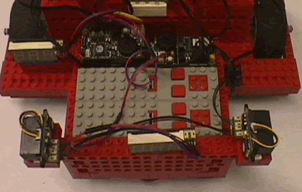
This view of the back of the
robot shows both of the crickets, two battery packs, and the
two back sensors (facing left and right). The crickets have
the capacity to run on a single 9-volt battery, however, we
discovered that random errors are more likely to occur when
the battery is getting weaker. Additionally, the strength of
the current supplied to the cricket varied based on how new
the battery was. By using a battery pack, of six 1.5-volt
batteries, the current supplied to the robot is more
consistent.
In the final version of the
robot, we only used one battery pack, attached to the
cricket controlling both driving motors and all five good
bathroom sensors. Additionally, we added one more
cricket. For an explanation of this decision, see the
Control
Flow
page.
|
Wheels
and Gearing
Our initial gearing included a pulley
mechanism as the first gear reduction. This had to be replaced
because it was causing significant slippage. We went through several
iterations of the gear train before constructing the current one. The
gear trains are encased in two towers which also provide the base for
the pushing mechanism. In order to accommodate the gearing system,
other minor modifications had to be made to the structure of the gear
towers. We are using a gear reduction of 9:1, which gives enough
torque to propel the weight of the structure while still maintaining
ample speed to navigate through maze within the allotted six minutes.
The gear train is comprised of 8-, 16-, and 24-tooth gears: an
8-to-24 gear pair from the motor, then a 16-to-16 pair for purposes
of spacing, and finally another 8-to-24 pair connecting directly to
the wheel.
We began by using Lego tires, with a
plastic center and a rubber outer ring, as our wheels. Under the
weight of the robot, the the flexible rubber part of wheels bulged,
causing a good deal of friction. In order to make the wheels more
solid, we filled the rubber outer rings with hot glue. Filling this
space lessened the bulging and decreased the surface area in contact
with the floor. The wheels then ran with less friction, but it was
difficult to maintain an even thickness of glue and to mold the it
such that the tire treads were straight.
The current robot uses a comercially
designed wheel with a thicker tire and a more solid construction. We
extended the base to allow for an extra beam on the outside of each
wheel to stabilize the wheels to keep them perpendicular to the
floor. In addition to the two wheels located near the front of the
robot, the base is supported by two casters, one at the back of the
base and one at the very front. These allow for easy turning with
minimal added friction.
|
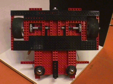
The picture to the right is a
view of the bottom of the robot. Since this picture was
taken, a slight modification has been made, changing the
placement of the two casters.
We were somewhat concerned with
the distribution of weight in the original design, in which
both casters were at the back of the base. Most of the
weight of the vehicle is contained in the shaving cream can,
the columns that hold the gear trains and support the
mechanism, and the pushing mechanism itself. All of this
weight was concentrated at the front of the
base.
Thus, if the robot was knocked
off balance at all, it may very well tip over and not be
able to recover and continue its run. Another factor to
consider is that we plan to enter the robot in the contest
in the "Non-Dead Reckoning" mode, in which ramps will be
placed in the hallways; we had to ensure that the robot will
be able to successfully go down the ramp without bottoming
out or tipping over. To alleviate this problem, we moved one
of the two casters from the back to the front, and centered
both of the casters.
|

|
Shaving
Cream and Pushing Mechanism
We were pleased with the pushing
mechanism that we created over Wintersession, and have kept it fully
intact. From the columns housing the gear trains, we built up two
hollow columns to which the pushing mechanism is secured. The
additional height was necessary because the shaving cream nozzle must
be higher than the 6" to 8" candle. Moreover, the base of the pushing
mechanism is deeper than the gear columns, so we made the hollow
columns larger to allow for a more secure attachment of the pushing
mechanism. As stability is one of our main goals in this structural
design, we felt that the additional size and weight of the two hollow
towers were worth the added stability they provided.
The can of shaving cream sits on top of
a simple platform built up from the base so that the nozzle is high
enough, anchored by Lego bricks at the corners of the platform.
Interestingly, the kind of shaving cream makes a important
difference. We found that Gillette Foamy, Original, shoots
significantly farther than any other brand we tried, allowing the
robot to extinguish the candle from a safe distance. Even other kinds
of Gillette Foamy (e.g., Sensitive Skin) failed to shoot far enough.
We still need to figure out exactly how far away the robot needs to
be from the candle in order to extinguish it reliably.
|

|
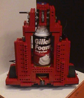
This front view of the robot
shows the two hollow columns onto which the pushing
mechanism is attached. The shaving cream is raised to the
proper height to extinguish the candle, and the space under
the can is being used to house the front distance sensor.
This seemed like a great place for that sensor for a number
of reasons. Since the distance sensors are accurate in
ranges greater than about 5cm, we wanted to ensure that a
wall was never closer than 5cm to the sensor.
|
Robot
Home
Introduction
Final
Robot
Structural
Design
Navigational
Systems
Misadventures


