CS307: Synthetic Cameras
Plan
- Synthetic camera and perspective projection
- Address quiz questions
- (paper/pencil) Exercise on perspective projection
- Projection matrices
- Three.js Camera API and camera tutor demo
- Exercises: Creating desired camera views
Pinhole and Synthetic Cameras
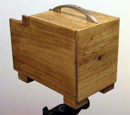
Pinhole camera, aka camera obscura:
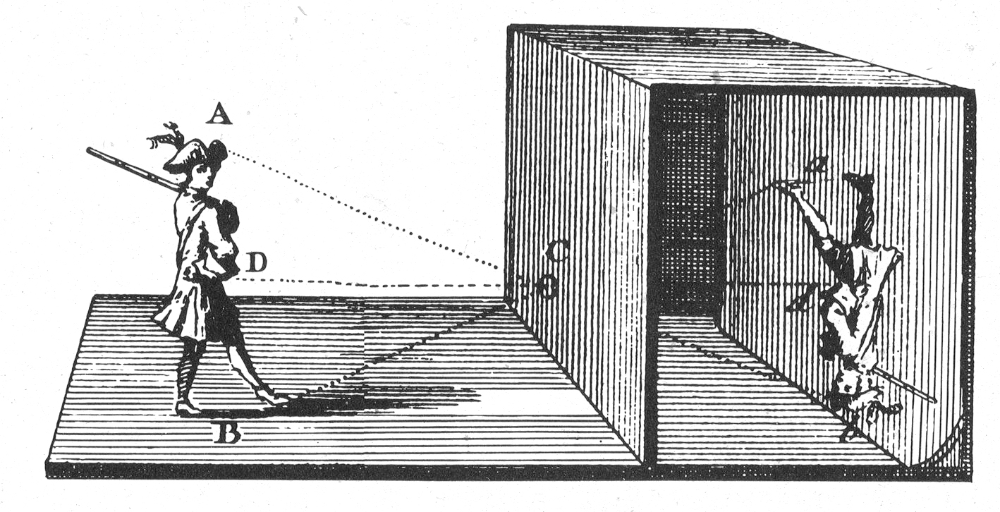
Pinhole camera with object and its projection:
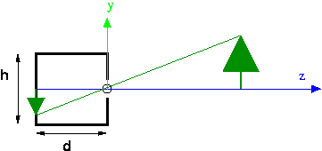
The synthetic camera moves the image plane in front of the center of projection to eliminate negatives:
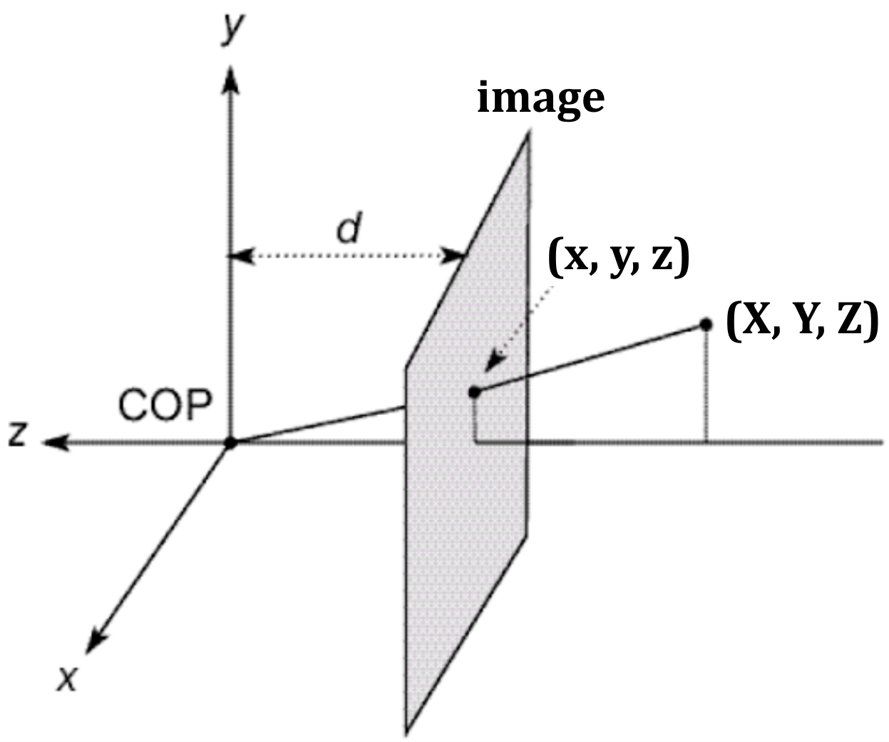
We'll use $(X,Y,Z)$ to refer to the 3D coordinates of a point in space, and $(x,y,z)$ to refer to the projected image coordinates. In the above diagram, the negative $z$ axis points to the right, so $z=-d$.
Consider the $y$ coordinate in the above pictures. Using similar triangles, $Y/Z = y/d$, so $y = d(Y/Z)$, which can be written as $y = Y/(Z/d)$
We can derive an expression for $x$ in a similar way: $x = X/(Z/d)$
Quiz Questions
Now is the time to address your questions.
Exercise: Perspective Projection
Example: With the standard camera (COP at the origin, looking down the negative Z axis) and the image plane at z=-3, find the projection of (7,8,-9).
Bird's eye view:
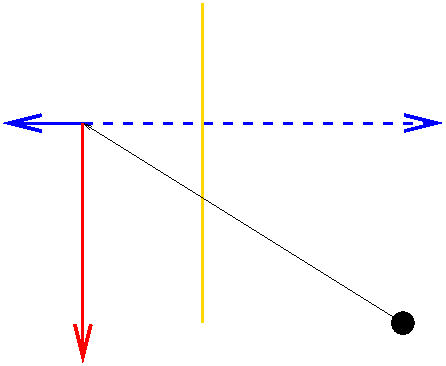
For X:
X/Z = x/z
7/-9 = x/-3
x = 7/3
For Y:
Y/Z= y/z
8/-9 = y/-3
y = 8/3
For the entire point, P:
projection of P
= (7/3, 8/3, -3)
Projection Matrices
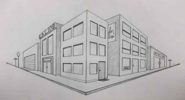
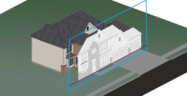
We've been focusing on perspective projection, which was used to generate the drawing below:
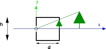
The following two images illustrate orthographic projection:
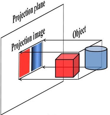
For orthographic projection, $(x,y,z) = (X,Y,0)$
Both projections can be implemented with matrix multiplication.
Orthographic Projection
\[ \left[ \begin{array}{rrrr} 1 & 0 & 0 & 0 \\ 0 & 1 & 0 & 0 \\ 0 & 0 & 0 & 0 \\ 0 & 0 & 0 & 1 \end{array} \right] \vecIV{X}{Y}{Z}{1} \]What does this do to a point $(X, Y, Z)$?
Perspective Projection
\[ \vecIV{X}{Y}{Z}{Z/d} = \left[ \begin{array}{rrrr} 1 & 0 & 0 & 0 \\ 0 & 1 & 0 & 0 \\ 0 & 0 & 1 & 0 \\ 0 & 0 & 1/d & 0 \end{array} \right] \vecIV{X}{Y}{Z}{1} \]To obtain the projected image coordinates, $(x, y, z)$, we divide the result on the left by $Z/d$ (the perspective division step), yielding the following:
\[ \vecIV{x}{y}{z}{w} = \vecIV{X/(Z/d)}{Y/(Z/d)}{d}{1} \]
Note that \(d\) is the near distance: the distance from
the COP (center of projection) to the image plane. (We'll think of
$d$ as a positive quantity here)
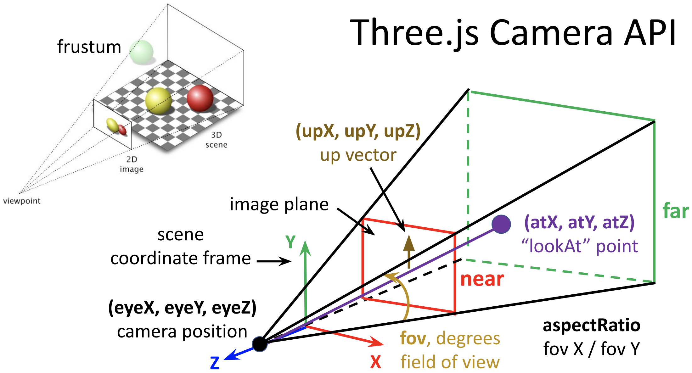
Camera Setup in Three.js
The diagram below summarizes the key elements of the camera setup:
In the above code example, the camera parameters (adjusted in the GUI) are stored in
an object named cameraParams:
var cameraParams = {
    near: 5,
    far: 30,
    fov: 75,                  // degrees
    aspectRatio: 400.0/300.0, // from canvas dimensions, see CSS
    atX: 0,
    atY: 0,
    atZ: 0,
    eyeX: 0,
    eyeY: 0,
    eyeZ: 25,
    upX: 0,
    upY: 1,
    upZ: 0
};
The following code defines a function named setupCamera() that creates
a camera with the desired parameters, and then invokes the function and adds the camera
to a scene:
function setupCamera (cameraParameters) {
    // set up an abbreviation
    var cp = cameraParameters;
    // create an initial camera with the desired shape
    var camera = new THREE.PerspectiveCamera(cp.fov,
                                             cp.aspectRatio,
                                             cp.near,
                                             cp.far);
    // set the camera location and orientation
    camera.position.set(cp.eyeX, cp.eyeY, cp.eyeZ);
    camera.up.set(cp.upX, cp.upY, cp.upZ);
    camera.lookAt(new THREE.Vector3(cp.atX, cp.atY, cp.atZ));
    return camera;
}
var camera = setupCamera(cameraParams);
scene.add(camera);
Note that you also need to do something like this at the end of your code:
function render() {
    // assume global variables scene, renderer, and camera
    renderer.render(scene,camera);
}
render();
TW's camera setup did this for us automatically. With this code, though, we can cut the TW apron strings.
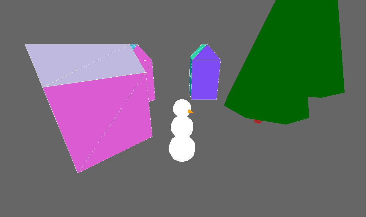
Exercises: Creating Desired Camera Views
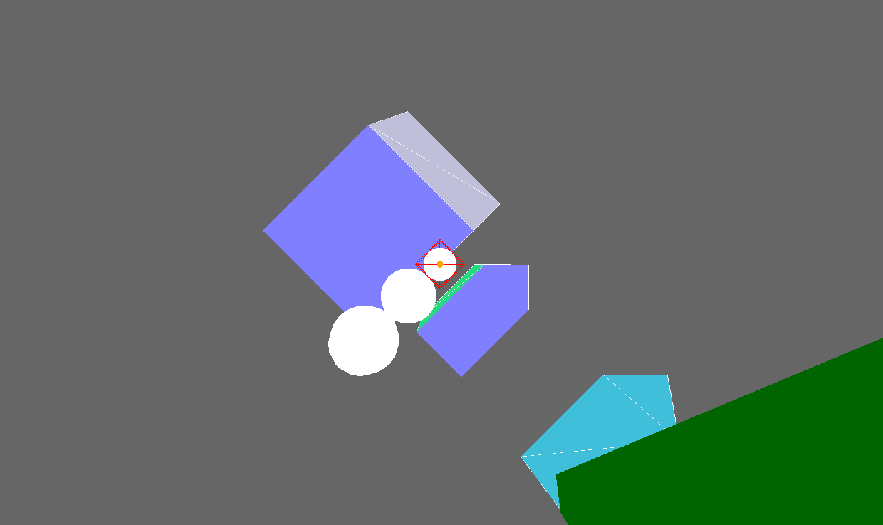
Exercise: Setting up a Camera
Using this town-view-before.html, set up a camera to view the snowman from above and to the right. Something like this:
- You might find it helpful to use the following town-view-gui.html .
- Define a function to set up the camera the way you want.
- Replace
TW.cameraSetup()with your new camera.
Your result might look like town-view.html
Exercise: Zooming vs. Dollying
Is there any difference between
- zooming in, keeping the eye point the same and reducing the FOV
- dollying in, keeping the FOV the same and moving the camera closer
Let's try to experience the effects of these changes to the camera setup.
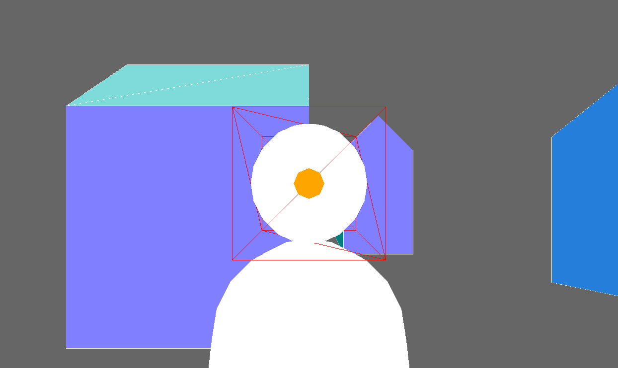
To begin, add a wireframe box to the scene that fits snuggly around the head of the snowman.
var boxGeom = new THREE.BoxGeometry(2*r1, 2*r1, 2*r1);
var boxMesh = new THREE.Mesh(boxGeom,
                  new THREE.MeshBasicMaterial({color: THREE.ColorKeywords.red,
                                               wireframe: true}));
boxMesh.position.set(3, r3+r3+r2+r2+r1, 9);
scene.add(boxMesh);
Then try to set the camera parameters so that the scene appears like this:
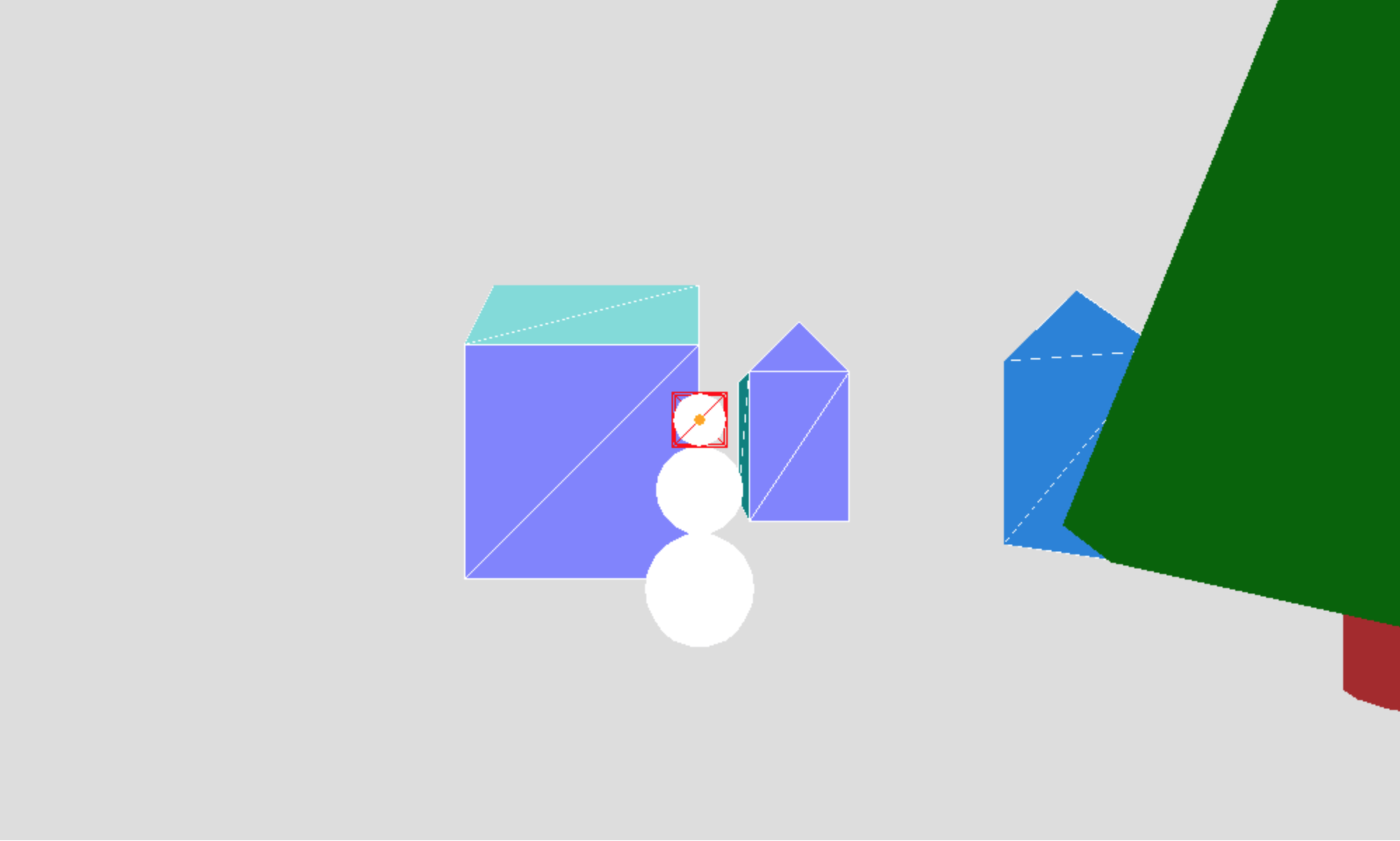
Hints: the camera is positioned 5 units in front of the center of
the snowman's head (at the same x and y coordinates as this center point) and is
looking at this center point. Set the fov to achieve the
above appearance.
Then try to set the camera parameters to reproduce each of the following views, dollying in to create one of the views and zooming in to create the other:
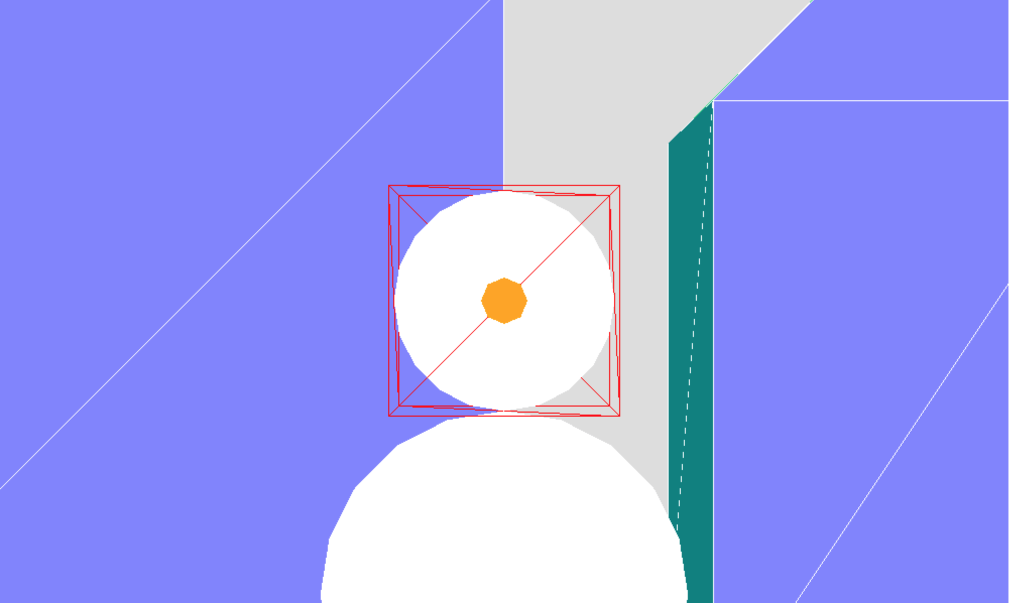
Which figure was created by zooming, and which by dollying?
Your solutions might be like snowman-close.html and snowman-zoom.html.
Vup
Most of the time, Vup is very simple: we have \[ V_\mathrm{up} = (0, 1, 0) \]
The minute we want something different, though, Vup can be confusing. Try to imagine it this way:
- Visualize the Vup vector in 3D space, along with the image plane.
- Project the Vup vector onto the image plane
- The frustum spins around the VPN (view plane normal) so that the Vup vector is parallel to the left/right edges.
- When the top of the frustum is mapped onto the canvas, the Vup vector is parallel to the left/right edge of the canvas.
There are two important consequences of the way Vup works:
- The Vup vector can't project to a point, which means it can't be parallel or anti-parallel to the VPN.
- Any change to the Vup vector that doesn't change the direction of its projection on the image plane doesn't affect anything. The image is still oriented the same way.
Exercise: Changing Vup
Let's try to experiment with changing Vup
Try to reproduce both of the following:
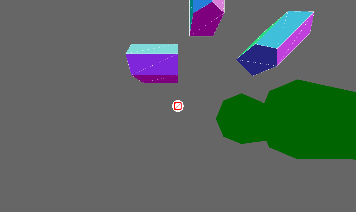
- Think about what Vup might be.
- Set up the camera for each scene.
Your solutions might be like snowman-close-angled.html and snowman-close-overhead.html.
Preparation for Next Time
Next time, we'll look at how we create surfaces with different material properties, such as dull or shiny surfaces, and how we add light sources to a graphical scene. To prepare:
- Reading for Tuesday: Material and Lighting