|
|
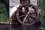
We were not sure how to go about to build our waterwheels so we went on Google and looked at pictures of waterwheels to get ideas. To the right are pictures of some of the waterwheels that we looked at. From looking at these we realized that the paddling parts of the wheel need not be very long; in fact except along the outer rim, paddles would only cause inefficiency. Other than paddles, support beams are required to hold the paddles in place. These also do not need to be more than just at the outer rim, where the force of the water against the paddles are the most strong.
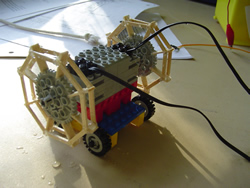
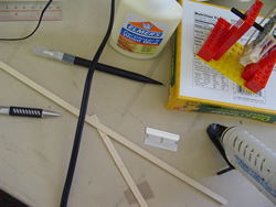
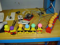
In in the end, we built the waterwheels out of 40-tooth LEGO gears and basswood planks. Each waterwheel has 8 paddles (1/16 in x 1/4 in x 2 cm) which are evenly spaced on the gear teeth, and each paddle is reinforced by octagonal braces on either side. We ended up gluing the spokes on with hot glue instead of the originally intended wood glue because hot glue enables drying before the paddles fall off. Afterwards, we painted the all the exposed wooden surfaces with clear nail polish to make it water-resistant.
Each water wheel is powered individually by a gray geared LEGO motor; thus, the two wheels can simultaneously turn in opposite directions and turn the ducky vehicle to the left or right.
To move a ducky forward, both its motors rotate forward; to move backwards, both motors rotate backwards; to turn left the right motor rotates forwards while the left motor rotates backwards and vice versa to turn right. The simultaneous turning of wheels in opposite directions provides very quick and efficient turning. This idea we would like to credit to classmate Anita Yip.
|
 |
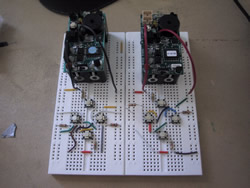
| Since there were only two sensor ports on the Blue Dots, and we needed something that could serve the function of four switches. We therefore built each remote out of a breadboard, four switches, four resistors with different resistances, and lots of wires. Each switch (a.k.a. button) corresponds to a different pathway and by pressing a switch you are closing the circuit, allowing the current to flow across the specific resistor. Thus, the current changes whenever a different switch is pressed. The circuit diagram is included to the right. In the end, we re-wired our remotes with aesthetic purposes in mind and so if the breadboard is unreadable, don't worry about it and just admire the "modern art". |
 |
Each of the towers are equipped with a distance sensor in the top of the indentation where the ping-pong ball sits. Whenever a ping-pong ball is knocked off the tower, the value of the distance sensor changes and the HandyBoard registers this change and turns on the motor. The connected LOGOChip, as the scoreboard, registers incoming current and thus knows that a score has been made.
To prevent the LEGO towers from floating, we weighed them down with LEGO lead weights at the bottom. The dimensions of the tower is 6FLU x 6FLU x 7-2/5FLU. Extension of the sensor cords was required to allow even placing throughout the large pool. |
 |
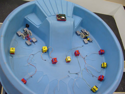
| We borrowed a kiddie pool from the Wellesley Children's Center as our water container. We filled the tub with approximately 2 inches of water, so that it was just enough for the ducks to float, but not enough to submerge the sensors on our towers. |
 |
|
|
 |